
A. Smaller wire in TW
Assumptions: Assume 0.0120 in ID and 0.0080 in finished wire.
Calculation: Subtract to obtain +0.0040 in diametral gap.
Next step: Nominal room exists; request limits and test the finished assembly.
Compare wall profiles and wire fit at 0.0180 in OD. Nominal screening; verify finished dimensions.
Request 26G drawing reviewOD fixed: 0.0180 in (0.457 mm). Defaults: TW + 0.010 in wire.
Change either field for an instant nominal result.
Calculated Tube ID
0.0120 in
0.305 mm (lumen: 0.0730 mm²)
Diametral Clearance
0.0020 in
0.051 mm
Positive nominal gap (≥ 0.0015 in). Geometric room exists under nominal conditions; verify worst-case tolerance stack, internal lubricious coating, and catheter tortuosity.
Radial gap: 0.0010 in (0.025 mm) per side.
2.07× RWEmpty-lumen conductance
88.7% RWUncut bending inertia (I)
0.014 in wire: no nominal gap in the RW, TW or 0.0020 in wall examples. A larger gauge also needs a verified minimum bore.
Nominal examples: Vita RW/TW chart. Custom walls are assumptions. The 0.0015 in diametral gap boundary is a display heuristic, not a validated fit criterion. Verify finished dimensions, tolerance stacks and tracking before selecting a part.
Calculation method & formulas| Finding | Decision | Basis / limitation |
|---|---|---|
| 0.014 in wire: no gap in RW/TW/XTW examples | Change bore or mating wire before prototyping. | ID − wire OD gives −0.0040, −0.0020 and 0.0000 in respectively. |
| TW empty-lumen conductance: 2.07× RW | Compare pressure loss and structural requirements together. | (0.012 / 0.010)⁴, same length, viscosity and pressure; no wire in lumen. |
| TW bending inertia: 88.7% of RW | Check buckling, fatigue and bending in the assembly. | Annular section calculation with identical material; not measured pushability. |
| Bare tube OD: approximately 1.37 Fr | Request the receiving component minimum ID. | French converts OD only. Jacket thickness increases the finished OD. |
| No pressure or joint rating from gauge | Define acceptance tests for the finished device. | ISO scopes and the manufacturer’s risk assessment; see validation scope below. |
Basis: Vita nominal dimensions, derived formulas, and ISO catheter scope.
Do not combine a supplier gauge suffix with an assumed ISO wall class. These references answer different questions; use a controlled drawing for procurement.
| Reference | Verified information | Still to confirm |
|---|---|---|
| Vita 26RW / 26TW stock chart | 0.0180 in OD; 0.0100 / 0.0120 in ID; chart lists ID +0.0010/−0.0005 in. | Availability and purchase limits. Wall is a reference dimension in this chart. |
| Hamilton 26 / 26s chart | 26: 0.464 mm OD, 0.260 mm ID. 26s: 0.474 mm OD, 0.127 mm ID. | Supplier variants differ; 26s is not an interchangeable wall preset. |
| ISO 9626:2016 | Rigid stainless steel needle tubing scope; flexible tubing is excluded. | Licensed dimensional table and agreed requirements for the selected product. No certified ISO wall mapping is claimed here. |
| ASTM A908-24 | Hard-drawn stainless needle tubing specification; inch-pound units govern. | Applicable grade, edition and dimensional requirements. Supplier chart tolerances are not attributed to ASTM here. |
RW/TW use the cited supplier nominal examples. XTW and ultra-thin below are explicit custom assumptions, not universal stock or ISO designations.
| Profile | Wall | Calculated ID | Lumen area | Flow ratio | Bending inertia |
|---|---|---|---|---|---|
| 26RW | 0.0040 in | 0.0100 in (0.254 mm) | 0.0507 mm² | 1.00× RW | 100.0% RW |
| 26TW | 0.0030 in | 0.0120 in (0.305 mm) | 0.0730 mm² | 2.07× RW | 88.7% RW |
| 26XTW / extra-thin example | 0.0020 in | 0.0140 in (0.356 mm) | 0.0993 mm² | 3.84× RW | 70.1% RW |
| Custom ultra-thin example | 0.0015 in | 0.0150 in (0.381 mm) | 0.1140 mm² | 5.06× RW | 57.2% RW |
Equal outer scale; wire shown concentrically for illustration. Nominal dimensions from the Vita chart; ratios are calculated with the listed formulas.
All gaps are diametral (ID − wire OD). “Positive” means geometric room in the nominal model, not a verified running fit. For other gauges, choose the bore first: a 25G RW/TW tube can still be too small for a 0.014 in wire.
| Wire OD | RW (0.0100 ID) | TW (0.0120 ID) | Custom XTW (0.0140 ID) | Next step |
|---|---|---|---|---|
| 0.0080 in | +0.0020 | +0.0040 | +0.0060 | Review minimum finished ID and maximum wire OD. |
| 0.0100 in | 0.0000 | +0.0020 | +0.0040 | RW has no nominal gap; review TW/custom bore. |
| 0.0120 in | −0.0020 | 0.0000 | +0.0020 | Review the custom bore or reduce mating OD. |
| 0.0140 in | −0.0040 | −0.0020 | 0.0000 | All three have no usable nominal gap. Review a larger finished bore. |
Interference / zero gap: change geometry.
Tight nominal gap: tolerance review required.
Positive nominal gap: still verify tracking.
These categories match the tool. The 0.0015 in boundary is a display heuristic, not an acceptance standard or clinical criterion.
Hypothetical drawing limits below illustrate gap consumption; they are not supplier capability claims or ASTM limits. Prefer measured minimum finished bore when available.
| Parameter | Assumption | Worst case |
|---|---|---|
| Bare OD | 0.0180 ± 0.0004 | 0.0176 minimum |
| Uniform wall | 0.0030 ± 0.0003 | 0.0033 maximum per side |
| Derived bare ID | OD min − 2 × wall max | 0.0110 minimum |
| Finished wire OD | 0.0100 +0.0004/−0.0002, coating included | 0.0104 maximum |
| Diametral gap | 0.0110 − 0.0104 | 0.0006 (radial gap 0.0003) |
| Ovality, internal liner, bends | Not included in this simplified stack | Additional reduction unknown; measure finished bore and test. |
Hagen–Poiseuille predicts pressure loss for steady laminar Newtonian flow in an empty, straight, rigid circular tube. It excludes the wire, slots, connectors, bends and assembly leakage. Bending inertia compares geometry at equal material modulus; it is not a measured buckling or fatigue result.
| Profile / ID | Viscosity assumption | 100 cm | 150 cm |
|---|---|---|---|
| RW / 0.0100 in | 1 cP | 23.7 psi | 35.5 psi |
| RW / 0.0100 in | 11.8 cP | 279.2 psi | 418.8 psi |
| TW / 0.0120 in | 1 cP | 11.4 psi | 17.1 psi |
| TW / 0.0120 in | 11.8 cP | 134.7 psi | 202.0 psi |
| Custom XTW / 0.0140 in | 11.8 cP | 72.7 psi | 109.0 psi |
1 cP is an assumed reference liquid. The 11.8 cP example comes from the U.S. VISIPAQUE label, section 11.2, 320 mg iodine/mL at 37°C (2025 label, reviewed 2026-10-29). Formulations and temperature matter. Use the applicable device IFU and assembly pressure verification.
Discuss 26G flow and drawing requirementsPattern geometry changes load paths. The following is a qualitative design checklist, not a ranked or tested 26G performance comparison; no torque percentages, minimum bend radii or universal laser settings are supported by the evidence used here.
| Geometry | Potential benefit | Trade-off / verification |
|---|---|---|
| Continuous helix | Spring-like compliance | Check wind-up, axial opening and fatigue. |
| Interrupted bridges | Retains connected load paths | Measure directional bending and torque response. |
| Interlocking features | Mechanical travel limits | Check backlash, contact stress, wear and particles. |
| Uncut tube | Simpler manufacturing and continuous fluid boundary | Check stiffness mismatch; consider a polymer or other shaft design if flex is insufficient. |
Skives, overlaps and jackets can distribute stiffness changes, but no angle or overlap length guarantees joint strength. At bare 26G OD (0.4572 mm), do not apply a force from an unrelated ISO size band.
| Option | Design variables | Evidence needed |
|---|---|---|
| Skived polymer overlap | Angle convention, overlap, edge radius, adhesive/reflow process | Conditioned pull test, kink and separation location. |
| Welded core / collar | Alloy pair, weld size, penetration, heat input | Weld inspection, pull and cyclic bend tests. |
| Reflow jacket over slots | Jacket thickness, liner, bonding and slot intrusion | Finished bore, leakage, burst and particulate testing. |
ISO 10555-1:2023 preview, clause 4.9: below 0.55 mm, the manufacturer sets a risk-based tensile acceptance criterion. Determine the applicable effective test-piece OD and junction conditions for the actual assembly.
| Candidate | Decision question | Required evidence |
|---|---|---|
| 304 / 304V stainless | Does the temper support required forming and stiffness? | Mill chemistry, temper and final-tube tensile/elongation results. |
| 316L / 316LVM stainless | Does the finished process meet corrosion and joining needs? | Surface treatment, corrosion and joining validation. Grade alone does not establish implant suitability. |
| Nitinol | Is recoverable bending required at the intended temperature? | Transformation temperature, shape setting, fatigue, surface and nickel-release assessment. No kink immunity is implied. |
| Cobalt alloy / specialty tubing | Does any strength benefit justify cost and processing changes? | Availability, joining, machining and final assembly test results. |
This is an RFQ checklist. Grade-level property ranges and comparative fatigue claims are withheld because no matching tube-level dataset is available in this review.
French = OD (mm) × 3. Bare 26G is 0.4572 mm × 3 ≈ 1.37 Fr. A catheter labeled 1.7 or 2.0 Fr describes an outer profile; obtain its actual minimum finished ID to assess nesting.
| Assumed minimum receiving ID | Bare 0.0180 in tube gap | Jacketed 0.0190 in tube gap | Action |
|---|---|---|---|
| Unknown (only French OD supplied) | Unknown | Unknown | Request minimum finished ID; do not infer compatibility. |
| 0.0170 in | −0.0010 in | −0.0020 in | Both examples interfere. |
| 0.0190 in | +0.0010 in | 0.0000 in | Jacketed example has zero gap. |
| 0.0220 in | +0.0040 in | +0.0030 in | Nominal geometric room; review maximum OD, bends and tracking. |
Hypothetical examples demonstrate the arithmetic and the next decision. They are not patient cases, bench-test records or demonstrated clinical outcomes.
Assumptions: Assume 0.0120 in ID and 0.0080 in finished wire.
Calculation: Subtract to obtain +0.0040 in diametral gap.
Next step: Nominal room exists; request limits and test the finished assembly.
Assumptions: Assume 0.0015 in wall at 0.0180 in OD.
Calculation: ID = 0.0150 in; wire gap = 0.0010 in.
Next step: Tight nominal gap. Compare a larger verified bore or smaller wire before committing to tooling.
Assumptions: Use the explicit hypothetical limits in section 5.
Calculation: Minimum ID 0.0110 − maximum wire 0.0104 = 0.0006 in.
Next step: Nominal 0.0020 in clearance is misleading; agree finished bore limits and tracking criteria.
Assumptions: Assume 11.8 cP, 150 cm and 1.0 mL/min; no wire.
Calculation: Calculated pressure losses: RW ~419 psi; TW ~202 psi.
Next step: Compare geometry, then test flow and pressure in the assembly. No safe injection setting follows from this calculation.
| Risk | Consequence | Mitigation / alternative |
|---|---|---|
| Nominal gap used as fit approval | Binding after coating or bending | Obtain finished limits and functional sliding-force tests; change bore or wire size. |
| Flow model used as pressure rating | Leakage or assembly failure | Use rated components and device IFU; verify flow, leakage and pressure on the assembly. |
| Unqualified cut / joint geometry | Kink, fatigue, separation or particles | Inspect cut quality and perform conditioned mechanical tests; compare uncut or alternative shaft constructions. |
| Tighter tolerances / thinner custom walls | Yield, inspection, minimum order and lead-time costs may rise | Ask for separate stock/custom quotations, first articles and capability data. No fixed cost multiplier is assumed. |
| Material grade substituted for device suitability | Corrosion, fatigue or contact mismatch | Review final processing and biological evaluation for contact type/duration. |
Raw rigid stainless needle tubing scope. Dimensional selection does not qualify a laser-cut flexible catheter.
General requirements for sterile single-use intravascular catheters. Evaluate the applicable assembly tests and intended-use requirements.
Passivation using electropolishing. It does not establish the roughness, finished bore or cleanliness acceptance of this tube; agree these separately.
Particulate matter in injections. It is not blanket catheter certification; document any rationale for adapting an extraction method or limit to the device.
Editions and scope checked 2026-10-29. This page is a dimensional screening aid, with no verified clinical performance, pressure rating, material-property dataset or universal acceptance criteria.
| Field | What to provide | Supplier response to request |
|---|---|---|
| Dimensions | Finished OD/ID min/max, length, wall and ovality controls | Feasible limits, measurement method and first-article report. |
| Material | Alloy, temper, joining and contact requirements | Traceable mill and final-tube evidence. |
| Coating / surface | Inside/outside layers, final roughness and particle requirements | Thickness allowance, inspection access and extraction method. |
| Pattern / joints | Controlled drawing, datum and angle conventions, acceptance tests | DFM proposal, cut inspection and prototype test plan. |
| Mating components | Minimum receiving bore, maximum finished wire and tube OD | Worst-case clearance analysis and tracking test proposal. |
| Commercial | Prototype/annual volume and required delivery date | Stock versus custom price, tooling, minimum order and lead time. |
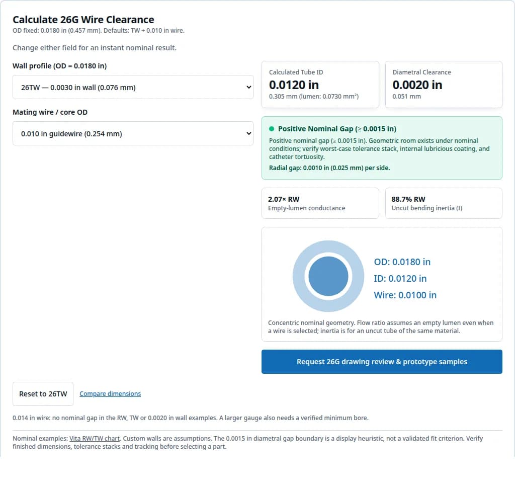
Geometry and ratios update synchronously in your browser; no network request or loading state is needed. The pressure table uses the same deterministic model as the chart. These are derived values, not experiments.
| Metric | Formula | Limits / units |
|---|---|---|
| ID / area | ID = OD − 2t; A = π × ID² / 4 | OD fixed at 0.0180 in; area displayed in mm². 1 in = 25.4 mm. |
| Gap | Diametral C = ID − wire OD; radial gap = C / 2 | Concentric straight geometry. No worst-case tolerances in the live tool. |
| Flow ratio | Q / Q_RW = (ID / 0.0100)⁴ | Empty smooth circular lumen; same length, viscosity and pressure. Not annular wire-occupied flow. |
| Bending second moment I | I = π × (OD⁴ − ID⁴) / 64 | I / I_RW approximates EI ratio only for identical modulus and uncut geometry; not polar moment. |
| Pressure loss | ΔP = 128 × μ × L × Q / (π × D⁴) | SI inputs: Pa·s, m, m³/s; Pa ÷ 6894.757293168 → psi. Q = 1 mL/min = 1/60,000,000 m³/s. |
| Display categories | C ≤ 0: fail; 0 < C < 0.0015 in: tight; C ≥ 0.0015 in: positive | UI heuristic only. No wire shows N/A clearance. No clinical fit criterion is inferred. |
Known: nominal examples, arithmetic and cited standard scopes. Unknown: current stock, price, capability, finished compatibility, fatigue, pressure rating and clinical suitability. Resolve these through the drawing, supplier evidence and finished-device verification.
Sources checked 2026-10-29. Manufacturing comparisons are qualitative prompts for verification where no matching test data are publicly established here.
This tool fixes nominal OD at 0.0180 in (0.4572 mm), matching the cited Vita 26RW/TW examples. Gauge alone is not a purchase specification; confirm actual OD and ID limits on the supplier drawing.
French size = OD in mm × 3, so 0.4572 mm is approximately 1.37 Fr. This converts the bare tube outer diameter only. A receiving catheter’s French OD label does not establish its lumen ID.
The modeled RW ID is 0.0100 in and TW ID is 0.0120 in, using ID = 0.0180 − 2 × wall. These are nominal supplier examples; measured bores and tolerances govern fit.
No. The 0.0020 and 0.0015 in walls here are custom screening examples. Supplier suffixes vary: Vita lists 26XV at 0.0135 in ID, which is different from this tool’s 0.0140 in XTW example. Confirm availability, minimum order and finished dimensions.
No. ISO 9626 concerns rigid stainless needle tubing. The calculator uses supplier nominal examples, not a certified ISO wall-class mapping; confirm the selected standard edition and drawing requirements before ordering.
It interferes with the RW and TW examples and has zero nominal gap in the 0.0020 in wall example. A 0.0015 in custom wall gives only 0.0010 in nominal diametral gap. Evaluate the finished minimum bore, maximum wire OD and bends before choosing a tube.
A 0.008 in wire leaves 0.0020 in in RW and 0.0040 in in TW. A 0.010 in wire leaves zero gap in RW and 0.0020 in in TW. Positive nominal clearance is a starting point for tolerance and tracking review, not demonstrated compatibility.
Minimum bore, maximum finished wire diameter, liners, swelling, ovality and bending can consume the gap. Use finished dimensions to avoid counting a coating twice, then verify sliding force in the intended assembly.
No. It is a display heuristic for nominal diametral gap, not a clinical or industry acceptance criterion. Set application-specific minimum clearance and friction criteria from tolerance analysis and functional tests.
Yes, as a manufacturing feasibility study. Kerf, strut width, recast, thermal damage and remaining wall must be qualified on the actual alloy and geometry. This page supplies no validated laser recipe or minimum bend radius.
No. Retained bridges change load paths, but torque response depends on pitch, strut dimensions, length, material, jacket and loading. No comparative 26G torque test data are supplied here.
Specify the required flexibility, torque, fatigue and push/pull performance first. Ask the fabricator to propose and test a pitch transition. The schematic is qualitative and is not a production pattern.
No. ASTM B912 addresses passivation using electropolishing. Specify and measure the required roughness separately, including an agreed method for the small bore. Recheck dimensions after material removal.
Do not assume zero thermal damage. Ask for process-specific microscopy and fatigue evidence. Pulse duration alone cannot establish the finished strut condition or a universal HAZ value.
It estimates pressure loss in an empty, straight, rigid circular tube at 1.0 mL/min. For the 11.8 cP viscosity example and 1.5 m length, RW is about 419 psi and TW about 202 psi. These are calculated losses, not safe injection limits or device ratings.
No. The cited ISO scope concerns rigid stainless needle tubing and excludes flexible tubing. Finished catheter qualification needs the applicable device standard, intended-use requirements and assembly-level verification.
Request the alloy, temper, dimensions, corrosion and fatigue evidence for the intended duty. No grade alone establishes biocompatibility, kink recovery or a guaranteed tensile strength in a finished 26G tube.
ISO 10555-1:2023 clause 4.9 leaves acceptance below 0.55 mm to the manufacturer’s risk assessment. Select the applicable effective test-piece OD and junction conditions; do not transfer a force value from another size band.
Include finished OD/ID limits, wall or eccentricity controls, length, alloy and temper, surface and coating requirements, pattern drawing, mating component limits, volumes and acceptance tests. Ask for capability and first-article evidence.
Unknown from gauge alone. Do not use this sizing tool to establish a pressure rating. Slots, jackets, joints, defects and conditioning affect the final assembly; obtain the specified pressure tests and device instructions for use.
FAQ uses the same assumptions as the tool. Sources and formulas: methodology above.
Inquiry Email
Best for drawings, tolerance tables, inspection needs, and quote history.
Instant Chat
WhatsApp Engineering Support
Fast path for OD/ID, material, sample quantity, and lead-time questions.