
Medical Hypotube End-Forming: Flaring, Swaging, Bulging vs. Welded Hub Collars in Catheter Design and Sourcing
Compare medical hypotube end-forming, welded collars, and bonded hubs. Review forming risks, wall thinning and verification inputs; prepare a drawing-based RFQ.
Medical hypotube end-forming reshapes the end of a small metallic tube by flaring, annular bulging, swaging, or stepped expansion. These features can provide a lead-in, retaining shoulder, or diameter transition for a catheter joint. This guide helps device engineers and sourcing teams compare forming with welded collars and bonded hubs, identify drawing inputs, and request the evidence needed to qualify a route.
Core sourcing takeaway: Use flaring for a lead-in or shoulder, bulging for overmold retention, and swaging for diameter reduction or a controlled crimp. A welded collar remains a candidate when expansion would compromise the shaft temper or lumen. None of these routes establishes a pressure or pull-force rating by geometry alone. Compare quotations against the same drawing, incoming material condition, minimum remaining wall, usable bore, and finished-assembly verification plan.
Published and editorially reviewed: November 2, 2026. Scope: Global medical device OEM engineering, contract manufacturing (CDMO/CMO) operations, and component procurement. This article provides an editorial design-for-manufacturing (DFM) and quality verification framework. It does not establish universal lot pass/fail thresholds or regulatory submissions. OEMs must determine device-specific validation protocols for their clinical indications. The comparisons below are editorial DFM analysis, not results from supplier trials, customer devices, or an independent clinical review.
Start with our precision medical hypotube portfolio, balloon catheter shaft configurations, and micro-tube inspection capabilities. For custom flared, swaged, or bulged tube drawings, contact our engineering team for a DFM review.
1. The Proximal Hub & Distal Joint Dilemma: Forming vs. Welded Bushings and Adhesive Joints
A proximal tube-to-hub joint must transfer the loads and contain the fluid pressures specified for the device. A distal joint must preserve a usable lumen and transition into the core wire or polymer shaft without unacceptable stiffness changes or sharp edges. These interfaces need different acceptance criteria.
Three routes merit a drawing-based comparison:
- Adhesive bonding into a molded hub: A straight tube can fit an existing hub cavity. The design must control bond gap, surface preparation, adhesive dispensing and cure, and compatibility with fluids, sterilization, and aging.
- Laser-welded collar or bushing: A separate ring supplies a locating shoulder or retention feature without expanding the parent tube. Evaluate collar fit, weld penetration, lumen intrusion, heat effects, and downstream cleaning.
- Native tube end-forming: A flare, bead, or swaged feature uses the tube wall itself. It can eliminate a separate collar or metal joining operation, but the formed feature may still need an overmold, gasket, adhesive, or other hub assembly step.
Selection boundary: A continuous metal feature removes one possible joining interface; it does not prove superior fatigue, leakage, or burst performance. Forming can introduce cracks, wall thinning, ovality, or a softened transition. Qualify the complete assembly for the intended load path.
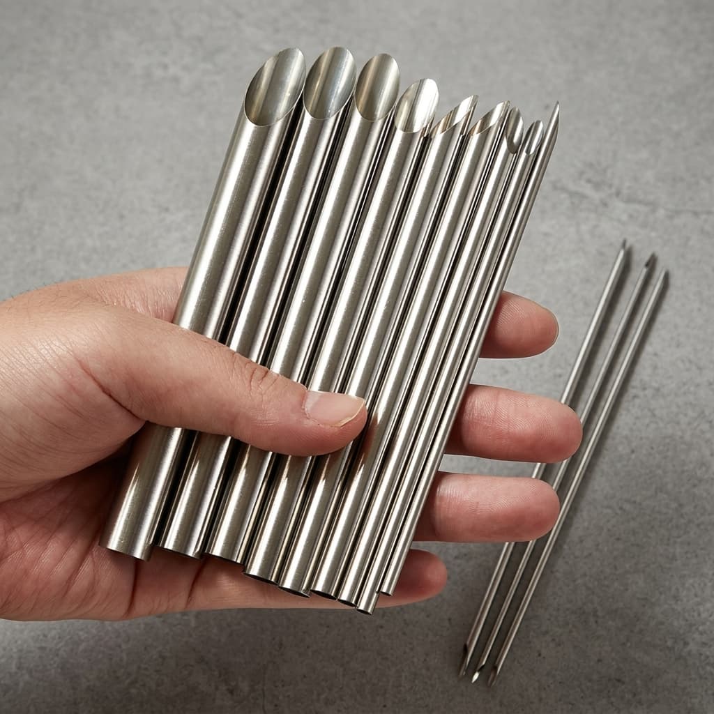
Illustrative product visual; not a measurement, inspection record, or customer test result.
2. Core End-Forming Geometries & Medical Device Applications
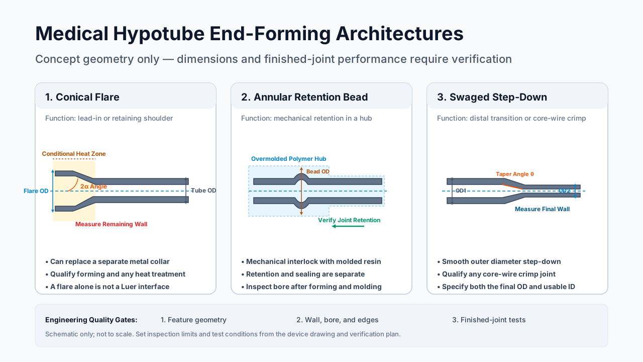
A. Conical Flaring: Lead-In or Retaining Shoulder
A punch or rotating mandrel expands the tube mouth. Define the included angle, mouth diameter, transition radius, and minimum wall on the drawing. A funnel can guide a wire or liner; a shoulder can retain the tube inside a hub.
A conical flare is not automatically a Luer connector. A flare angle and a Luer taper describe different geometries. If the formed metal surface is the actual mating interface, its dimensions and functional performance require separate assessment against the applicable ISO 80369-7 connector requirements.
B. Annular Bulging & Rib Beading: Overmold Retention
A raised annular bead can provide an axial interlock inside an overmolded hub or locate the tube during assembly. Specify bead diameter, width, axial position, and remaining bore. Retention depends on the bead, surrounding resin, molding quality, and assembly geometry; a bead alone does not establish a pull-force rating or a fluid seal.
C. Rotary Swaging & Necking: Diameter Reduction
Swaging reduces the outer diameter through controlled deformation. It can create a distal step-down or compress a tube around a core wire. The internal tool or core, axial material flow, and incoming dimensions determine the final bore and wall distribution. Specify OD and ID directly rather than relying on a gauge label.
D. Stepped Expansion: Telescoping Joint Preparation
A cylindrical mandrel expands the tube end to accept a liner or another shaft component. Set insertion depth, overlap, clearance, and bond or retention requirements together. An expanded ID does not guarantee a continuous flow path after the liner and joining materials are installed.
3. Visual Architecture: Medical Hypotube End-Forming Schematics
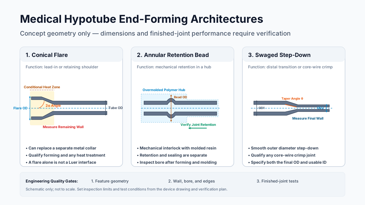
Concept schematic, not to scale and not evidence of validated dimensions, supplier capability, or measured performance. The highlighted heat-treatment zone is conditional on process development. For each geometry, the drawing must identify the feature, remaining wall, bore, and finished-joint verification requirements.
4. Material Temper & Formability Limits: The Full-Hard 304V Ductility Trade-Off
Cold drawing can increase shaft strength while reducing the ductility available for later forming. Alloy designation alone cannot establish whether an end can be flared or bulged. Request the incoming material condition, relevant test results, and a forming trial on representative tube stock.
For a simple geometric screen, engineering circumferential strain is e = (Df - D0) / D0, where D0 and Df are diameters at the same material location before and after expansion. A change from 0.65 mm to 0.95 mm gives e ≈ 0.462, or 46.2%. This is a geometric estimate, not an allowable forming limit. A tube tensile elongation result cannot be directly substituted for a multiaxial forming limit.
| Material / Process Condition | Engineering Implication | Evidence to Request Before Release |
|---|---|---|
| Annealed stainless tube | More forming ductility may be available, with a softer shaft | Material certificate, dimensional results, and shaft stiffness checks |
| Quarter-hard stock | Trade-off between shaft properties and forming demand | Supplier definition of temper and representative forming samples |
| Half-hard stock | Expansion remains dependent on tooling and geometry | Crack inspection, bore measurements, and final wall sections |
| Full-hard / heavily drawn stock | Expansion may exhaust available ductility | Trial results for the actual lot condition; no universal cold-expansion allowance |
| Locally heat-treated stainless end | May permit forming while retaining a harder parent shaft | Heat-treatment extent, transition characterization, and finished-shaft tests |
| Superelastic Nitinol tube | Springback and thermal history change the process choice | Material-specific shape-setting or forming development and final property verification |
Localized Annealing: Define the Outcome Before the Equipment
Induction and laser heating are possible process routes. The supplier should justify the thermal cycle, atmosphere, heat-treatment boundary, and cleaning sequence for the alloy, wall thickness, and required shaft properties. There is no universal temperature, dwell time, or boundary length for all medical hypotubes.
Sourcing decision rule: Ask a supplier proposing cold flaring to demonstrate feasibility on representative stock. Ask a supplier proposing localized annealing to demonstrate both end formability and acceptable properties across the heated transition. Neither an equipment name nor an unqualified temper label is sufficient release evidence.
5. Manufacturing & Sourcing Matrix: Comparing Four Hub Attachment Routes
Use this qualitative matrix to frame an RFQ. It is an editorial comparison of process dependencies, not measured performance, a price benchmark, or a supplier ranking. Keep the hub, load cases, sterilization, and acceptance criteria constant when comparing samples.
| Sourcing Dimension | Native Conical Flare | Annular Bead + Overmolding | Laser-Welded Collar | Adhesive Bond into Hub |
|---|---|---|---|---|
| Metal components | Tube; hub hardware may still be needed | Tube with retention bead | Tube plus separate collar | Tube; separate molded hub |
| Tooling / NRE inputs | Punch, collet, support, and trial effort | Bead tooling plus mold and insert handling | Collar manufacture, alignment, and weld fixtures | Dispensing, positioning, surface preparation, and cure fixtures |
| Production cycle inputs | Forming stages, any heat treatment, cleaning, inspection | Forming plus molding and handling | Fit-up, weld path, cleaning, inspection | Preparation, dispense, cure, inspection |
| Axial retention | Shoulder engagement and hub strength govern | Bead geometry and resin engagement govern | Collar geometry and weld quality govern | Bond area, gap, preparation, and cure govern |
| Leakage / pressure verification | Assess the actual seal and supporting hub | A mechanical interlock still needs a sealing strategy | Assess weld integrity and the separate hub seal | Assess bond continuity and fluid compatibility |
| Usable lumen risk | Local thinning, ovality, or tool damage | Bore distortion during forming or molding | Weld intrusion, oxidation, or misalignment | Adhesive migration into the bore |
| Sterilization / aging | Verify metal, hub, seals, and interfaces together | Verify resin and interlock after conditioning | Verify weld condition and other assembly materials | Verify adhesive and substrate compatibility after conditioning |
| Change-control focus | Incoming temper, tooling, heat treatment | Bead tooling, resin, mold parameters | Collar fit, weld parameters, cleaning | Surface treatment, adhesive batch, dispense and cure |
Practical shortlisting: Favor a flare when a lead-in or shoulder is needed and the expansion can be qualified. Evaluate a bead when the hub needs mechanical retention. Keep a welded collar in the comparison when forming or heat treatment would compromise the tube. Evaluate bonding when the hub design accommodates a controlled, inspectable bond. More than one route may meet the same device requirements.
For comparable quotations, request a drawing-based DFM review with the same joint load cases, sample quantities, and required inspection records for each candidate route.
6. Wall Thinning, Pressure Screening & Connector Verification
Wall Thinning: An Explicitly Simplified Example
For a thin wall and negligible axial strain, volume conservation gives the screening relationship tf ≈ t0 × Dm0 / Dmf, using mean-wall diameters at the same material location. Axial stretching, material feed, and tool contact can change the result; this is not a prediction of minimum flare-heel thickness.
Illustrative inputs: initial OD 0.65 mm and wall 0.08 mm give a mean diameter of 0.57 mm. If the final OD is 0.95 mm, solving tf × (0.95 - tf) ≈ 0.08 × 0.57 gives tf ≈ 0.0507 mm, about 36.6% thinning under these assumptions. These are hypothetical dimensions, not a forming trial or an approved drawing. Verify the actual minimum wall by an agreed sectioning or other suitable measurement method.
Pressure Screening Is Not a Burst Rating
For a straight thin-walled cylindrical region, the membrane relation hoop stress ≈ P × Dm / (2 × t) can screen stress at internal pressure P, mean diameter Dm, and wall t. It does not establish a flare burst rating: conical geometry, local thinning, residual stress, material condition, and hub contact change the stress state. An allowable stress, yield strength, and ultimate tensile strength are different quantities and must not be interchanged.
Test the finished tube-to-hub assembly under its intended support conditions. Specify pressure, medium, temperature, ramp and hold, cycling, sample plan, conditioning, and failure definition. A rigid fixture that supports the joint differently from the actual hub can conceal the intended failure mode.
Separate Three Verification Questions
- Does the mating connector meet its interface requirements? ISO 80369-7:2021 addresses small-bore intravascular or hypodermic connectors. It does not specify the performance requirements of every device using those connectors. Obtain the applicable edition and referenced methods for dimensions, leakage, and mechanical connector testing.
- Does the finished catheter meet its device requirements? ISO 10555-1:2023 addresses sterile, single-use intravascular catheters. Determine the applicable device-specific tests and joint acceptance criteria from the controlled standards and the device risk assessment.
- Does the assembly meet the program's intended pressure and load claims? Define and verify these separately. Passing a Luer interface test does not approve a high-pressure injection claim, a hub pull-off rating, or the bare formed tube.
The public standard catalogue records establish scope; they do not justify copying universal test pressures, clause numbers, pull forces, or hold times into a supplier drawing.
7. Distal Swaging & Step-Down Transitions: Core-Wire Attachment
Telescoping Diameter Reductions
A swaged transition can reduce an abrupt outer-profile step before a polymer shaft joint. Specify transition length, taper, final OD and ID, straightness, and liner clearance. Swaging redistributes material; the balance between wall change and axial elongation depends on tooling and restraint. Do not assume a fixed percentage of wall thickening or preserved buckling resistance.
Inspect the transition and evaluate the finished shaft for the relevant bending, kink, torque, or cyclic loads. A smooth external profile can still conceal a restricted bore or a locally stiff transition.
Core-Wire Mechanical Crimping
Define wire material, wire diameter, crimp location and length, and acceptable external profile. Develop the crimp process with representative tube and wire stock. Record pull-off behavior and the failure location, then check for wire damage, sharp ridges, and downstream jacket damage. Minimum retention and fatigue requirements must come from the device design; a generic coronary or neurovascular label does not establish a force threshold.
8. Failure Modes, Root Causes & Sourcing Prevention Matrix
These are failure hypotheses and inspection questions for process development, not measured defect frequencies or universal acceptance limits.
| Observed Defect / Failure Mode | Possible Mechanism | Assembly Concern | Supplier Evidence / Prevention |
|---|---|---|---|
| Longitudinal splits | Expansion exceeds available formability; damaged starting edge | Leakage, fragments, reduced retention | Incoming condition, edge preparation, forming trials, agreed crack detection |
| Roughened or fissured surface | Material structure or thermal/forming process is unsuitable | Reduced fatigue margin or surface damage | Characterize the material and thermal cycle; distinguish surface texture from cracks |
| Thin flare heel | Local stretching and tool contact concentrate deformation | Local rupture or loss of shoulder strength | Section representative samples; control minimum remaining wall and tool radii |
| Eccentric feature / excessive runout | Misaligned tooling or variable incoming wall | Uneven seating or assembly fit | Datum-based runout measurement and incoming wall assessment |
| Bore constriction / ovality | Inadequate support or uncontrolled material flow | Wire or liner interference; reduced fluid passage | Inspect the final bore and verify functional passage with the intended mating part |
| Burr or sharp rim | Starting cut, worn tooling, or displaced material | Jacket damage or particulate generation | Define edge condition and particle/cleanliness checks; validate the finishing process |
9. Engineering & Procurement RFQ Specification Checklist
Send the same package to each shortlisted supplier. Values must be set by the device drawing and verification plan, not copied from a generic article.
- 1. Alloy and incoming condition: Material specification and edition, OD/ID/wall tolerances, temper definition, certificates, and traceability. Confirm scope: ISO 9626:2016 concerns rigid needle tubing and excludes flexible stainless tubing; it is not a blanket catheter-shaft specification.
- 2. Formed geometry: Dimensioned drawing with flare angle or bead/step dimensions, transition radii, feature location, and mating parts.
- 3. Heat-treatment boundary: State whether heat treatment is allowed, the affected region, required parent-shaft properties, and how the transition will be characterized.
- 4. Minimum remaining wall: Identify critical locations and the measurement method. A minimum wall callout alone does not guarantee burst resistance.
- 5. Datums and alignment: Define feature runout, perpendicularity, straightness, and the measurement setup relative to the shaft and hub.
- 6. Edges and usable bore: Set burr/edge criteria and finished lumen requirements, including liner or core-wire fit.
- 7. Surface and process sequence: Agree cleaning, oxide removal or passivation where applicable, and coating sequence; check compatibility of all materials and residues.
- 8. Mechanical joint verification: Define load direction, specimen assembly, conditioning, loading method, acceptance criterion, and failure-location reporting.
- 9. Leakage and pressure verification: Separate connector-interface tests from finished-assembly pressure, cycling, and burst requirements; specify medium, temperature, and endpoints.
- 10. Quality and commercial package: Request first-article results, process traceability, relevant QMS documentation, tooling ownership, itemized NRE, sample quantities, inspection scope, and quoted lead times. Confirm which changes trigger requalification.
10. Frequently Asked Questions (FAQ)
Can full-hard 304V hypotubes be flared cold without localized annealing?
Possibly for a qualified geometry and process, but there is no universal safe expansion percentage. Request trials on the actual material condition and inspect the formed region. If heat treatment is needed, verify its effect on the adjacent shaft as well as on the end feature.
Is end-forming more reliable than a laser-welded hub collar?
It removes the collar weld when that interface is eliminated. It introduces different risks, including thinning and forming cracks. Compare both routes using the same hub design, loading, conditioning, and acceptance criteria; geometry alone cannot establish which is more reliable.
What tooling cost and lead time should an RFQ expect?
Request a quote separating forming tools, fixtures, process development, any heat treatment, inspection, and prototype quantities. Ask whether production tooling and rework are included. No universal NRE range, cycle time, or prototype lead time is established by the sources in this article.
Can an already coated hypotube be locally annealed?
Treat coating compatibility as a process constraint. Heat, atmosphere, cleaning, and forming can damage a coating or change adhesion. Agree whether forming precedes coating, whether a coating-free zone is needed, and how the finished transition will be inspected. A masking distance alone does not establish thermal protection.
Can Nitinol hypotubes use the same forming recipe as stainless steel?
Do not transfer a stainless steel recipe. Nitinol springback and thermal history require a material-specific development plan, potentially including shape setting. Verify final dimensions and required material behavior; this article specifies no universal shape-setting temperature or dwell time.
Does ISO 80369-7 compliance establish a high-pressure catheter rating?
No. It addresses the connector interface within its scope. Device and assembly requirements need separate verification, including the actual hub, tube, seals, and conditioning. Obtain the applicable controlled standard and define the intended device claims before releasing drawing criteria.
Engineering Support & RFQ Sourcing
For a custom flare, retention bead, or swaged transition, submit your drawing for an end-forming feasibility review. Include the alloy and incoming condition, OD/ID, target geometry, mating hub or liner, allowed heat-treatment zone, quantities, and required verification records. The review should confirm process feasibility and quote assumptions before tooling release.
- Explore the medical hypotube product range for tube selection inputs.
- Review balloon catheter shaft configurations when defining the joint load cases.
- Discuss 5-axis laser cutting where formed features interact with cut shaft patterns, and micro-tube inspection for the required measurement package.
Sources & References
Editorial source check: November 2, 2026. These primary catalogue records define the relevant standards' scope. Public abstracts do not replace the controlled texts or device-specific verification, and they do not support supplier-specific cost or performance claims.
- ISO 80369-7:2021 — Connectors for intravascular or hypodermic applications: Official ISO record. Scope: dimensions and functional performance of the connector interface, rather than a pressure rating for every device incorporating it.
- ISO 10555-1:2023 — Intravascular catheters, general requirements: Official ISO record. Scope: sterile, single-use intravascular catheters; determine the applicable requirements for the finished device.
- ISO 9626:2016 — Stainless steel needle tubing: Official ISO record. Applies to rigid needle tubing; flexible stainless tubing is outside its stated scope. Check revision status before specifying an edition.
- ASTM A632-19 — Small-diameter austenitic stainless steel tubing for general service: Official ASTM historical-edition record. A general-service tube specification, not proof of medical-device suitability. The catalogue marks this edition historical; agree the applicable edition and supplementary requirements with the supplier.
Limitations and maintenance: This is a DFM and procurement framework, not physical test evidence, a process recipe, or regulatory clearance. The device owner must establish applicable standards, risk controls, and verification criteria. Review at the next drawing release and at least annually; reassess when material condition, geometry, tooling, joining process, coating, sterilization, or intended use changes.
Author

Categories
More Posts
Radiopaque Marker Bands: Platinum-Iridium vs. Gold for Catheter Visibility
A technical comparison of Pt-Ir, Gold, and Tantalum marker bands, with critical RFQ tolerancing guides for catheter assembly.
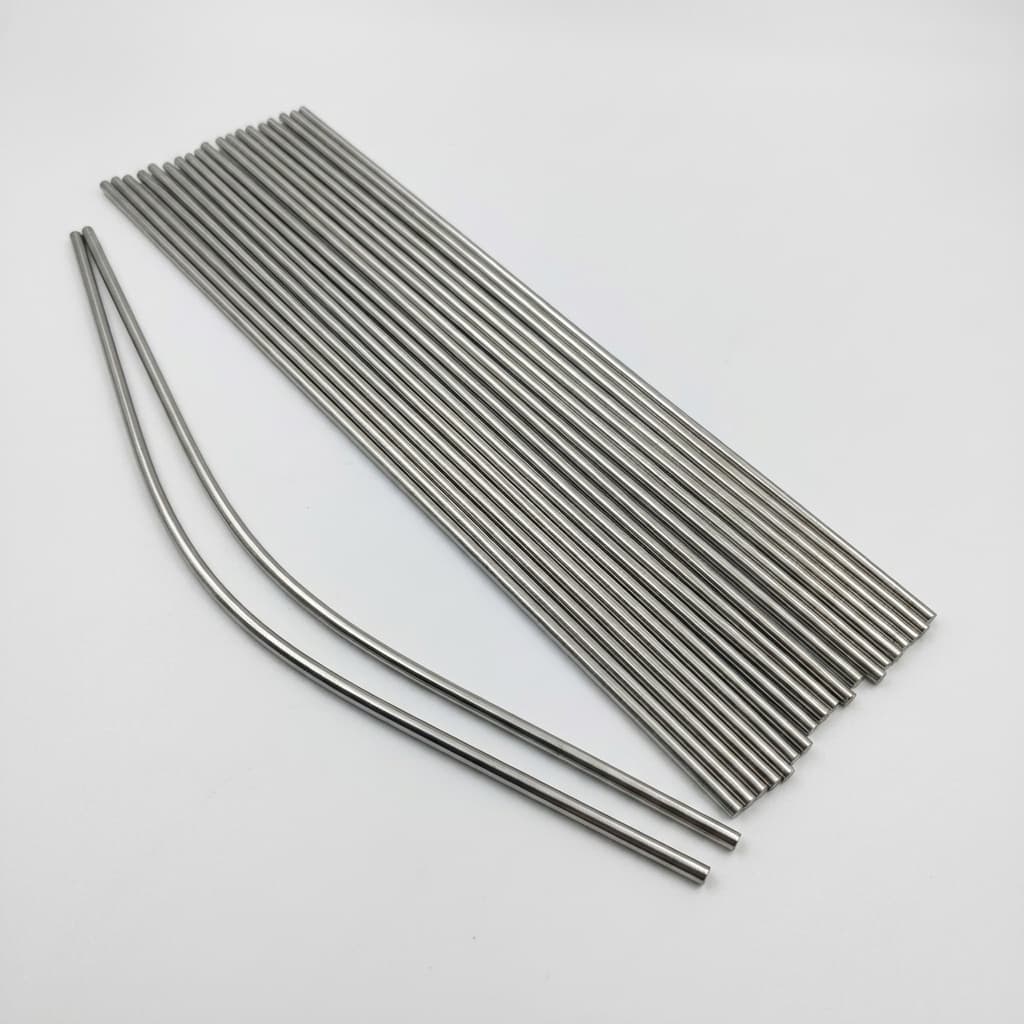
Navigating FDA QMSR and EU MDR Compliance in Medical Hypotube Sourcing: A 2026 Guide
2026 guide to FDA QMSR and EU MDR impacts on medical hypotube sourcing, supplier audits, material traceability, and compliance evidence.
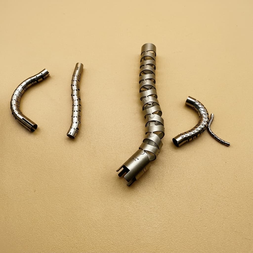
Endoscope Snake Bone Tubing: Monolithic Laser-Cut Bending Sections vs. Riveted Vertebrae
Compare endoscope snake bone tubing designs, material trade-offs, fatigue validation and RFQ inputs. Prepare a drawing-based DFM review with Medical Hypotubes.