
Seamless vs. Welded & Drawn Medical Hypotubes: Metallurgy, Laser Cutting Yield, Burst Pressure, and Sourcing Economics
Compare seamless vs welded-and-drawn medical hypotubes for metallurgy, laser cutting yield, pressure testing, and sourcing cost. Request a drawing-based DFM review.
When interventional device engineers and procurement teams compare seamless vs. welded-and-drawn medical hypotubes, the useful question is which manufacturing route can meet the finished component's requirements with repeatable evidence. The route affects the process risks to investigate; it does not establish catheter performance by itself.
Core sourcing takeaway: Evaluate both seamless (SMLS) and welded-and-drawn (W&D) stainless steel tubing against the same drawing, finished-part tests, and cost per accepted component. Seamless removes the longitudinal weld as a potential defect location. Qualified welded-and-drawn stock can be a practical alternative when its bore, wall distribution, laser-cut features, and pressure performance meet the application requirements. Neither label guarantees superior yield, fatigue life, or pressure capability.
Published and editorial review date: November 6, 2026. Scope: Global medical device OEM engineering, contract manufacturing, and component procurement; primarily 304/316-family stainless steel tubing. This is a design-for-manufacturing (DFM) and sourcing framework, not a device qualification report. Nitinol requires a separate alloy-specific assessment. The public standards summaries cited below establish scope; the responsible quality team must review the applicable full editions and device requirements before defining acceptance criteria.
Method and evidence limits: This comparison combines manufacturing-route analysis with a proposed qualification workflow and explicitly hypothetical calculations. No comparative production trials, supplier quotations, measured scrap rates, or customer outcomes are reported. The calculations help identify what to measure; they do not establish supplier capability, clinical safety, or regulatory conformity.
Explore our precision medical hypotube portfolio, medical stainless steel tubing specifications, 5-axis laser cutting capabilities, and micro-tube inspection guidance. For a drawing review and sample evaluation plan, contact our engineering team.
1. Manufacturing Origins: Billet Extrusion vs. Strip Roll-Forming & Plug Drawing
Manufacturing history helps engineers decide what to inspect before attributing a cutting or assembly problem to the tube route.
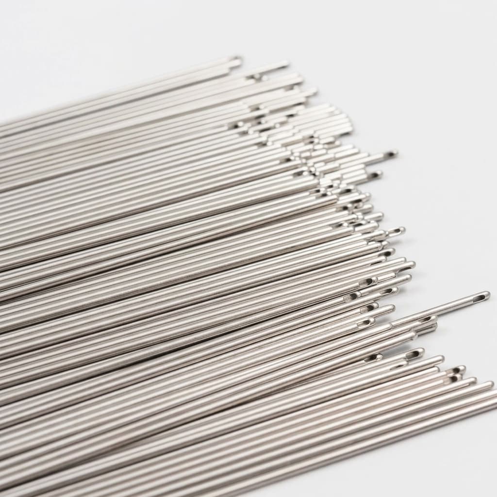
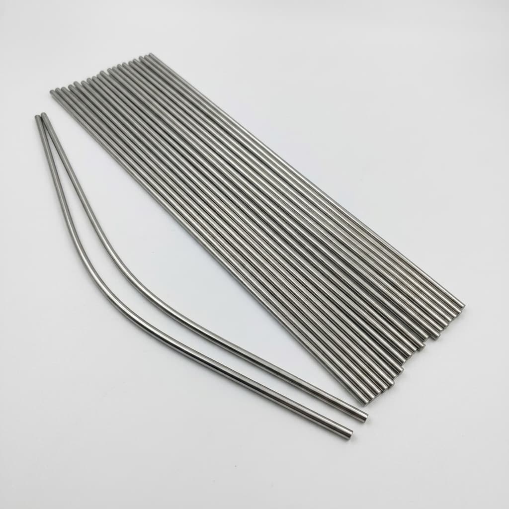
AI-enhanced product illustration; not evidence of alloy grade, temper, measured dimensions, or supplier qualification.
Seamless Hypotube Fabrication
- Create a hollow starting tube: Seamless processing starts from a hollow produced without a longitudinal weld, using methods such as piercing, extrusion, or drilling, depending on alloy and mill practice.
- Reduce diameter and wall: Cold pilgering and drawing operations bring the tube toward its required dimensions. Internal tooling, reduction schedules, and starting eccentricity influence the final bore and wall distribution.
- Control material condition: Intermediate annealing and final cold work establish the specified temper. Cleaning and finishing follow the agreed process route.
- Verify the result: Absence of a weld eliminates a weld-specific discontinuity, but seamless stock can still contain drawing damage, inclusions, eccentric wall, or residual stress. It is not automatically isotropic.
Welded-and-Drawn Hypotube Fabrication
- Form and weld strip: Precision strip is roll-formed into a tube and joined longitudinally, for example by laser or gas tungsten arc welding. Strip condition and weld control both matter.
- Distinguish the drawing operations: Sink drawing uses an external die without internal support. Plug or mandrel drawing also controls the bore and can reduce the weld-root profile. Actual suppliers may use combinations of these operations.
- Control annealing and final temper: Drawing and appropriate heat treatment can modify the original weld microstructure. They do not prove that every weld discontinuity has disappeared.
- Specify the finished bore: Do not accept a process label as a substitute for bore geometry, surface condition, and functional clearance. If internal tooling is essential, require a documented route as well as measurable final requirements.
ASTM A269/A269M and ASTM A632 address both seamless and welded austenitic stainless tubing. They are general-service specifications, not blanket approval for a catheter component. Confirm dimensional coverage, material condition, supplementary requirements, and edition in the purchase specification.
2. Engineering Comparison: The 8-Point Specification Matrix
The matrix identifies evidence to request rather than universal supplier tolerances or industry yield averages.
| Engineering parameter | Seamless hypotube | Welded-and-drawn hypotube | Procurement / DFM acceptance evidence |
|---|---|---|---|
| Longitudinal weld | No longitudinal weld | Welded region remains part of the process history | Route declaration, traceability, and relevant defect assessment |
| Wall distribution | Depends on hollow quality and reductions | Depends on strip, forming, weld, and reductions | Minimum wall and circumferential wall map at agreed positions |
| OD, ID, and ovality | Drawing-dependent | Drawing-dependent | Drawing limits, sampling locations, calibrated method |
| Microstructure and temper | Cold work can introduce texture and residual stress | Weld, annealing, and cold work can introduce local differences | Lot mechanical results; sectioning or hardness maps where justified |
| Laser cutting yield | Removes seam-related variation; other defects remain possible | Requires assessment of seam interaction with the selected pattern | Accepted count / started count using defined defect criteria |
| Pressure performance | Depends on geometry, properties, defects, and assembly | Depends on the same variables plus weld integrity | Device-specific leak, proof, burst, and cycling protocols |
| Bore / guidewire clearance | Bore may still contain scoring or contamination | Bead profile and drawing marks require verification | Bore profile, finish method, cleanliness, and functional passage test |
| Cost and availability | Stock and custom-draw options vary | Stock and custom-draw options vary | Comparable written quotes, quantity tiers, qualification cost, delivery terms |
Wall variation, concentricity, and total indicated runout (TIR) are different measurements. Define the datum, units, sectioning method, and calculation on the drawing. A percentage wall variation cannot be substituted directly for a TIR limit in millimetres.
3. Visual Engineering Architecture
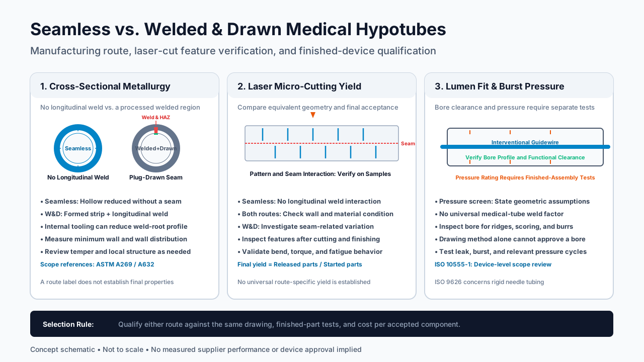
The schematic illustrates manufacturing differences and the verification steps that connect them to a purchasing decision.
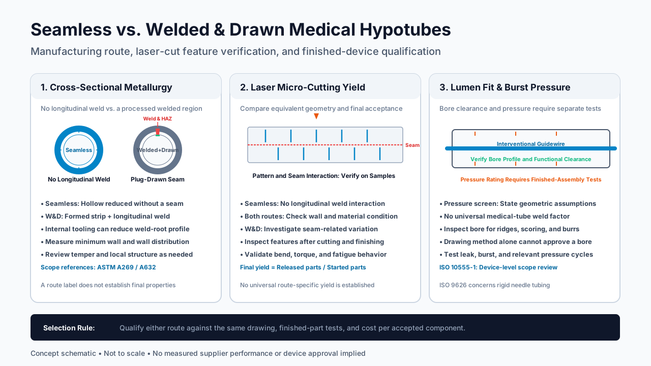
Concept schematic, not to scale and not evidence of validated dimensions, supplier capability, or measured performance. Acceptance limits belong on the component drawing and qualification protocol.
4. Metallurgical Deep Dive: Microstructure, HAZ, and Mechanical Isotropy
Grain Structure and Heat-Affected Zone
Welding creates a fusion region and an adjacent heat-affected zone (HAZ). Subsequent reductions and heat treatment can alter that structure. The remaining differences depend on alloy, weld parameters, deformation, and thermal history; there is no universal hardness difference or grain-size range for all W&D medical hypotubes.
Seamless tubing also acquires a processing history. Cold work can produce directional properties, and uneven wall or residual stress can affect bending response. Consequently, neither route should be described as guaranteeing a homogeneous, isotropic finished shaft.
If seam-related behavior is a credible failure mechanism, request a metallographic cross-section and an appropriately designed microhardness traverse. Record preparation, indentation load, location, and wall thickness so the result is interpretable. Set acceptance criteria from the component's requirements and qualification evidence, rather than adopting an unsupported percentage hardness limit.
Torque Transmission Depends on the Whole Shaft
For an ideal, uncut circular tube, the polar second moment of area is:
J = pi × (Do^4 − Di^4) / 32Torsional stiffness also depends on shear modulus and length: GJ/L. A laser-cut pattern, polymer jacket, transitions, friction, and contact with surrounding anatomy change the assembled response. The uncut-tube expression cannot predict a cut catheter's rotational tracking on its own.
Compare distal rotation, lag, and recovery under controlled bending and friction conditions representative of the intended use. Test multiple rotational orientations when directional bias matters. Seamless removes one potential source of asymmetry; it does not guarantee immediate 1:1 torque transmission or eliminate whipping.
5. Laser Micro-Cutting Performance: Strut Yield & Fatigue Mechanics
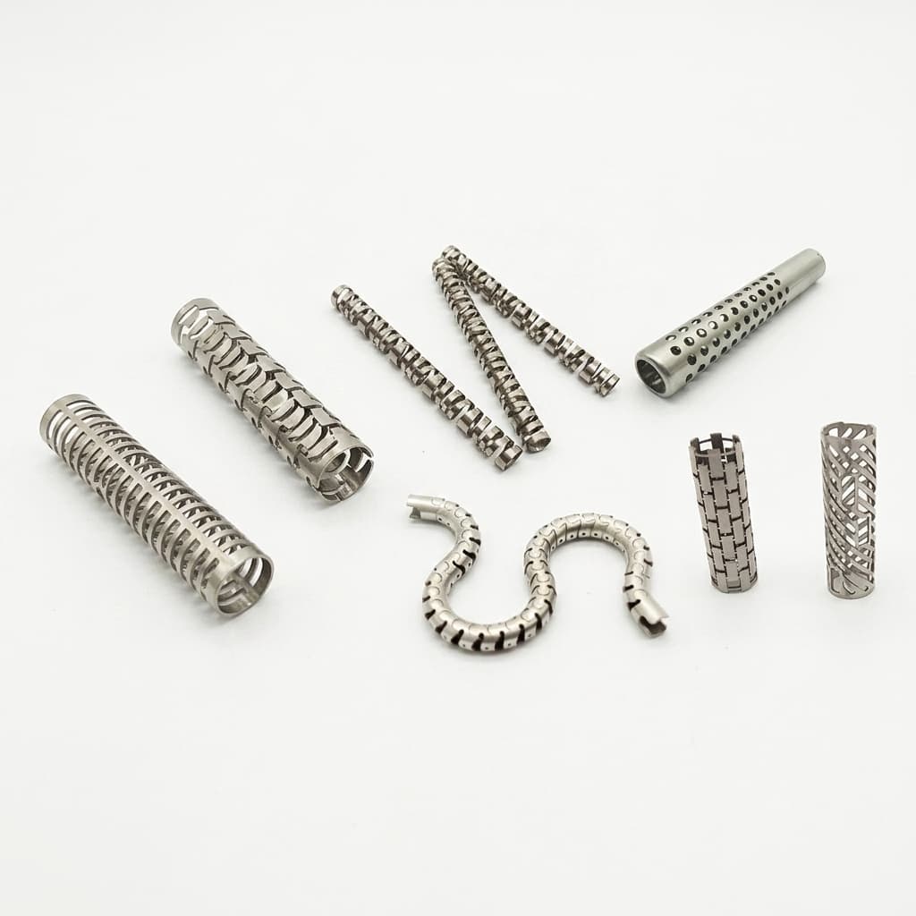
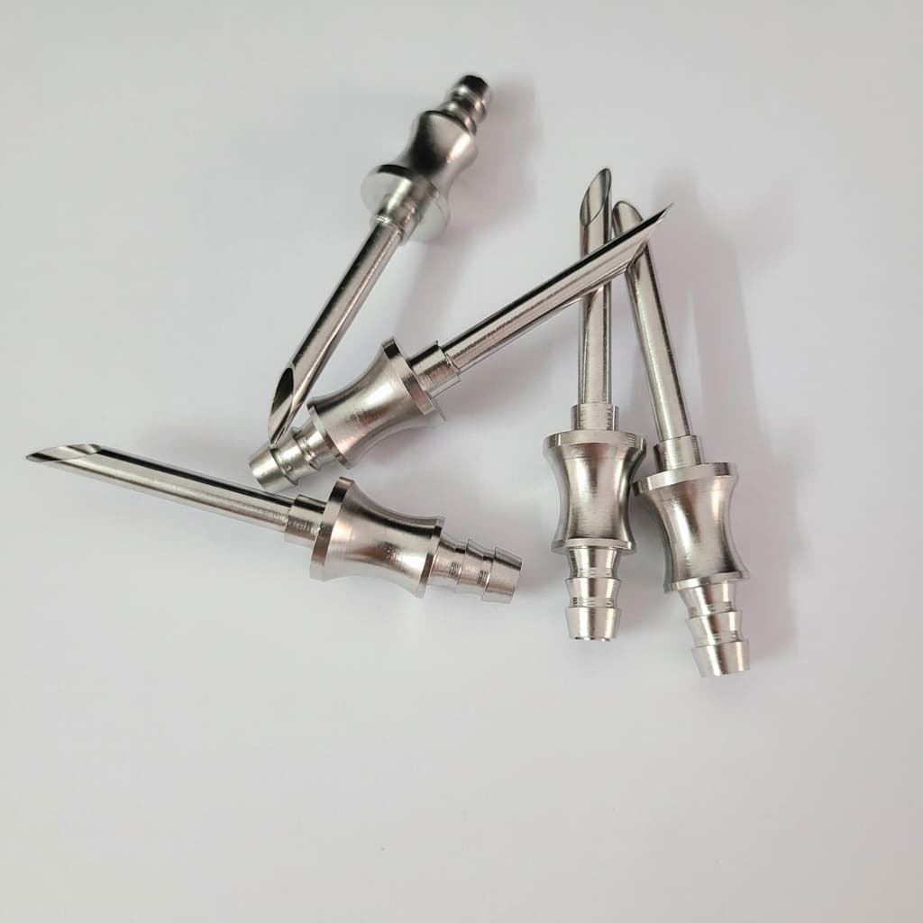
Product-pattern illustration; no kerf, minimum strut, production yield, or fatigue capability is established by this image.
A cut path may intersect the longitudinal weld, depending on the pattern and tube orientation. Local geometry, surface condition, or weld discontinuities can then interact with cutting and finishing. Seamless stock still requires checks for eccentric wall, material variation, fixturing, recast, and handling damage. Shorter pulse duration may reduce thermal damage under a qualified process, but it does not repair a pre-existing material defect.
A Practical Comparison Trial
- Match the specification: Compare alloy, temper, OD, ID, minimum wall, length, and surface condition. Record lot identity and measured variation so a wall difference is not misreported as a route effect.
- Control processing: Use the same pattern, inspection definitions, and finishing endpoint. Record laser parameters, fixturing, and seam orientation where known. If each route receives a different optimized recipe, report that distinction.
- Count defects by stage: Separate cutting rejects, finishing rejects, and final mechanical failures. Define final yield as released components divided by started components, with any rework counted explicitly.
- Test the finished feature: Inspect strut geometry after finishing, then evaluate bending, torsion, and fatigue appropriate to the device. A visually acceptable cut is not proof of fatigue life.
- Report uncertainty: Retain sample counts, lot coverage, failure locations, and confidence limits. A small pilot with no rejects cannot establish a commercial 99% yield claim.
No universal strut-width threshold establishes when seamless becomes necessary. Use the actual pattern, wall, finishing allowance, and measured failure mechanism. For trial planning, request a laser-cutting DFM review with both the tube specification and finished-part drawing.
6. Hydraulic Burst Pressure: Barlow's Equation & Safety Factors
Separate a Stress Screen from a Burst Rating
A thin-wall, Barlow-style relation can provide an approximate hoop-stress screen for a straight, intact tube:
sigma_hoop ≈ P × Do / (2 × t)Here P is internal pressure, Do is outside diameter, and t is the minimum remaining wall after relevant processing. Use consistent units. This approximation assumes a thin, circular wall away from cuts, transitions, and end effects. Thicker walls, local features, or other loading require a more appropriate analysis.
Substituting an assumed ultimate tensile strength into the inverse equation does not establish a validated burst rating. Plasticity, defects, residual stress, fatigue, bonds, and fittings can govern failure. Likewise, a pressure-vessel joint efficiency of 0.85 is not a universal derating rule for welded medical hypotubes. Eddy-current inspection does not assign such a factor, and seamless tubing does not receive automatic device approval from a factor of 1.00.
Hypothetical Wall-Thickness Sensitivity Example
Assume an intact tube with Do = 0.700 mm, minimum wall t = 0.030 mm, and internal pressure P = 8.0 MPa (approximately 1,160 psi). The diameter-to-wall ratio is about 23; this example uses a thin-wall screen only:
sigma_hoop ≈ 8.0 × 0.700 / (2 × 0.030) = 93.3 MPaIf the minimum wall is instead 0.025 mm, the same approximation gives 112 MPa, a 20% increase. Both routes produce the same arithmetic with those inputs. The calculation illustrates sensitivity to minimum wall, without establishing allowable stress, safety margin, rated pressure, or survival probability.
Qualify the Finished Pressure Boundary
Define pressure, hold duration, temperature, medium, pressure rise, conditioning, leakage detection, and failure criteria in an approved protocol. Include finished assemblies and relevant pressure cycles or post-bending conditions. Record whether failure occurs in the tube, weld, transition, fitting, or bond.
ISO 10555-1:2023 covers general requirements for sterile, single-use intravascular catheters. Its public catalogue entry does not establish a universal proof multiplier or a raw-tube pressure rating. Select the applicable tests from the controlled standard and device risk assessment. Aspiration additionally requires assessment of vacuum collapse and kink behavior; positive-pressure arithmetic does not answer that question.
7. Inner Lumen Clearance & Guidewire Tracking
An internal weld-root profile is one possible obstruction. Bore scoring, ovality, debris, end burrs, coating variation, and assembly transitions can also increase drag in either route. Plug or mandrel drawing can improve bore geometry, but the process name alone does not establish a smooth or snag-free lumen.
Specify a minimum usable bore and the compatible guidewire or instrument envelope, including coatings and tolerance accumulation. Define surface roughness with its measurement method, evaluation length, and access limitations. If a project chooses an ID roughness target such as Ra ≤ 0.4 µm, identify it as a project requirement; do not present it as a universal ISO 9626 rule.
ISO 9626:2016 concerns rigid stainless steel needle tubing. Its scope excludes flexible stainless steel tubing, so a laser-cut flexible catheter shaft needs a separate applicability review. Compliance with a rigid-needle tubing specification does not establish finished catheter trackability.
For incoming inspection, combine process records with representative bore examination and a functional passage or drag test using the intended mating component. Sectioned microscopy can reveal geometry but cannot alone prove which drawing method was used. A straight pin gauge checks accessible clearance; it does not reproduce a coated guidewire passing through a bent assembly.
8. Sourcing Economics: Total Cost of Ownership (TCO) & Supply Chain Strategy
A lower tube price can be outweighed by downstream scrap, qualification, or inventory costs. Compare equivalent delivery conditions, traceability, inspection scope, and finishing before comparing quotations.
| Sourcing factor | Seamless question | Welded-and-drawn question | Decision rule |
|---|---|---|---|
| Tube price | Is this stock or a dedicated draw? | Is internal drawing and specified inspection included? | Compare price per usable component at the same order quantity |
| MOQ and tooling | What is the minimum lot and tooling charge? | Can existing strip and tooling meet the drawing? | Obtain written minimums; avoid assumed industry ranges |
| Delivery | Is approved material available now? | Is approved material available now? | Separate stock shipment, custom processing, and qualification lead time |
| Laser / finishing yield | Which defects remain after processing? | Is seam-associated rejection demonstrated? | Use measured final yield with the same release definition |
| Quality cost | What documentation and sampling are included? | What weld evidence and defect detection are included? | Include inspection, qualification, and rework costs |
| Continuity and change | Can an alternate mill match the approved condition? | Can an alternate mill match strip, weld, and draw controls? | Qualify the alternate source and agree change notification |
Hypothetical Cost per Accepted Part
Assume all started parts incur the stated conversion cost and scrap has no recovery value. The example excludes rework, inspection, freight, and qualification:
Cost per accepted part = (tube cost + conversion cost) / final yield
Seamless: ($4 + $40) / 0.98 = $44.90
Welded-and-drawn: ($2 + $40) / 0.94 = $44.68
These are illustrative inputs, not quotations or measured yields. Despite the four-percentage-point yield difference, W&D remains slightly cheaper in this example. Its break-even yield is about 93.55%; at 92%, its cost rises to $45.65. Thus, a claimed five-point scrap reduction does not automatically justify a route premium. Recalculate with actual stage costs, failure timing, qualification amortization, and forecast volume.
Commercialization and Change Control
Qualify the intended production route early enough to avoid an unnecessary late material change. If a prototype route differs from production, define an equivalence plan covering dimensions, mechanical condition, laser processing, finish, and assembled performance. Route changes should go through the manufacturer's quality and regulatory assessment; the impact on submissions depends on the device, jurisdiction, and change. A second source is useful only after its capability and documentation have been established.
9. Failure Modes, Root Causes, and Quality Control Prevention
The possibilities below are investigation prompts, not diagnoses from a symptom alone.
| Observed failure | Possible contributors in either route | Additional W&D question | Verification before corrective action |
|---|---|---|---|
| Directional bending or whipping | Wall variation, cut pattern, residual stress, assembly friction | Does behavior correlate with seam orientation? | Wall map and repeated orientation-dependent assembly tests |
| Guidewire drag | Ovality, burrs, debris, scoring, coating buildup | Is a weld-root profile reducing clearance? | Bore examination and representative bent-path passage test |
| Strut cracking | Recast, finishing damage, geometry, fatigue loading | Is the crack associated with the welded region? | Locate fracture origin; compare finished features across lots |
| Leakage or early rupture | Minimum wall, local damage, bonds, fixtures | Is there an identifiable weld discontinuity? | Controlled pressure test, failure location, metallographic investigation |
| Nested assembly binding | OD, bow, ovality, contamination | Is weld geometry contributing to local ovality? | Datum-based dimensional checks and actual assembly trial |
| Cracking during flaring | Excessive cold work, tooling damage, expansion demand | Does cracking follow the seam? | Forming trials on the specified material condition and process |
Non-destructive inspection requires a defined technique, calibration reference, detection limits, and acceptance criteria. A claim of “100% inspected” describes coverage, not certainty that every defect is detected. Pair inspection with appropriate destructive and functional evidence where required by the risk assessment.
10. The 10-Point Engineering & Procurement RFQ Checklist
Use this checklist to obtain comparable quotations and a reviewable sample plan:
- 1. Manufacturing route: State seamless or welded-and-drawn, and any required plug/mandrel operations. Require traceability and change notification.
- 2. Alloy and condition: Specify grade, chemistry, melt requirements where needed, temper, and applicable material specification with edition.
- 3. Mechanical properties: Define tensile, yield, and elongation requirements, test method, specimen constraints, and reporting basis for the actual size.
- 4. Geometry: State OD, ID, minimum wall, ovality, length, and relevant wall-distribution or runout definitions with datums. Avoid contradictory tolerance stacks.
- 5. Surface and cleanliness: Define bore and external finish, measurement method, burr limits, contamination criteria, and any post-finishing dimensional checks.
- 6. Straightness: Define the supported length, measurement setup, and allowable bow relevant to feeding and assembly.
- 7. Defect inspection: Specify coverage, method, calibration, acceptance criteria, and records. Ask what the method cannot reliably detect.
- 8. Functional qualification: Define responsibility for leak, pressure, fatigue, bend, torque, and guidewire testing applicable to the finished device.
- 9. Secondary operations: Supply the laser-cut pattern, finishing allowances, end conditions, and stage at which critical dimensions are accepted.
- 10. Documentation and commercial terms: Request lot-linked material and dimensional results, certificate scope, sample quantity, annual forecast, MOQ, tooling, and confirmed delivery.
A quality-system certificate concerns the supplier's certified system and scope. It is not a substitute for component conformity or device approval. Keep component release evidence linked to the approved drawing revision and manufacturing lot.
11. Frequently Asked Questions (B2B Engineering & Sourcing Scenarios)
Can welded-and-drawn hypotubes safely handle 1,200 psi power injection?
That pressure cannot be approved from the manufacturing route alone. Qualified W&D tubing may be suitable, but dimensions, minimum wall, material condition, defects, bonds, and the finished assembly determine performance. Plug drawing and eddy-current inspection alone are insufficient evidence. Use the applicable device protocol and acceptance criteria; the same obligation applies to seamless tubing.
Does this stainless steel comparison also apply to Nitinol?
Only the general practice of specifying requirements and verifying performance transfers directly. Nitinol has different thermal, joining, and transformation behavior, and requires its own material and process qualification. Do not use the stainless steel cost example, pressure assumptions, or route discussion to approve a Nitinol component, or infer that all Nitinol tubing must follow one manufacturing route.
Which route gives better wall concentricity?
Neither label establishes the answer. Strip thickness can help control the starting wall in W&D, while hollow quality and reductions influence seamless stock. Forming, drawing, and final processing affect both. Request measured circumferential wall data at agreed locations, distinguish it from TIR, and compare the guaranteed drawing limits.
Can incoming inspection prove whether the tube was plug-drawn?
A cross-section or bore profile can identify a ridge, scoring, or local geometry, but a finished surface alone does not conclusively establish the manufacturing history. Use supplier process records and traceability to verify the specified route, then inspect finished bore requirements and functional clearance independently.
Is welded-and-drawn stock always faster for prototypes?
No. Approved stock availability can matter more than the route. Either option may require a custom draw, tooling, special finishing, or additional inspection. Request separate dates for material availability, finished samples, documentation, and qualification instead of relying on generic week ranges.
When does laser cutting yield justify paying for seamless?
When measured cost per released part, including qualification and recurring quality costs, supports the premium and the route meets the device requirements. The hypothetical example above shows why a tube-price saving can survive a modest yield penalty. Confirm the failure mechanism before changing routes; process correction may be the appropriate response.
12. References and Technical Standards
These official catalogue records support the standards' identities and scopes. They do not substantiate comparative yield percentages, market share, pricing, or supplier-specific performance. Public summaries do not replace the controlled full text.
- ASTM International — ASTM A269/A269M-15a, austenitic stainless tubing for general service. Historical edition, not a claim of current-edition compliance. Its scope notes size-related mechanical-property limitations; specify the appropriate requirements for miniature tubing separately.
- ASTM International — ASTM A632-19, small-diameter austenitic stainless tubing for general service. Covers seamless and welded tubing. Historical edition reference; confirm the required edition and size coverage before ordering.
- ISO — ISO 9626:2016, stainless steel needle tubing. Applies to rigid needle tubing and excludes flexible stainless tubing. Review applicability before citing it for a catheter shaft.
- ISO — ISO 10555-1:2023, general requirements for sterile, single-use intravascular catheters. A device-level reference; raw tubing selection alone does not demonstrate conformity.
For each purchase specification, confirm editions, amendments, and market-specific applicability with the responsible quality and regulatory teams. Review this article when its cited standards or the relevant process assumptions change; an unchanged publication date does not establish that a purchased standard is current.
13. Next Steps: Evaluate Your Catheter Hypotube Sourcing
Bring the drawing, candidate material conditions, finished-part requirements, sample quantity, annual forecast, and required documentation to the sourcing discussion. If the route is still open, request separate seamless and W&D proposals against the same acceptance criteria. Include laser-cut and post-finishing samples when those operations govern performance.
Use the medical hypotube catalog to frame the component request and the 5-axis laser cutting capability page to identify features needing process review. Then request a drawing-based DFM review and sample quotation. The useful output is a documented feasibility assessment, proposed verification plan, and comparable quotation, with unresolved requirements identified before production approval.
Author

Categories
More Posts
Medical Hypotube Miniaturization: Navigating Ultra-Thin Walls for Neurovascular Catheters
Medical hypotube miniaturization guide for ultra-thin neurovascular catheter walls. Compare tolerances, materials, failure modes, and RFQ trade-offs.

Navigating PFAS Restrictions in Medical Device Coatings: Alternatives to PTFE for Hypotubes
A comprehensive guide for procurement and engineering teams on transitioning away from PTFE-coated medical hypotubes ahead of EU REACH PFAS restrictions. Evaluating silicone, hydrophilic, Parylene, and electropolished bare metal alternatives.
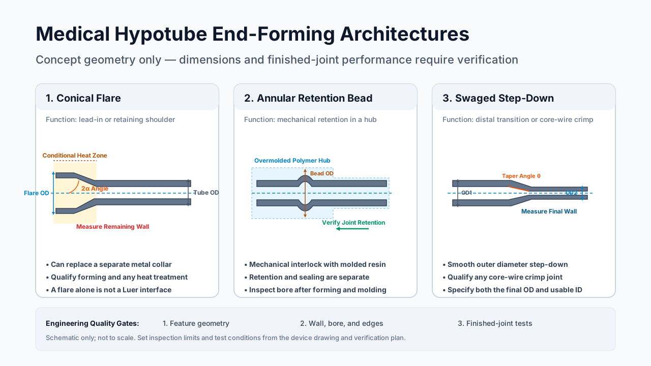
Medical Hypotube End-Forming: Flaring, Swaging, Bulging vs. Welded Hub Collars in Catheter Design and Sourcing
Compare medical hypotube end-forming, welded collars, and bonded hubs. Review forming risks, wall thinning and verification inputs; prepare a drawing-based RFQ.