
304 Hypotube Sizing & Alloy Guide
304 hypotube is small-diameter stainless tubing specified by alloy, dimensions and condition. Calculate nominal lumen and compare 304, 304L and 304V before drawing review.
Published · Evidence reviewed
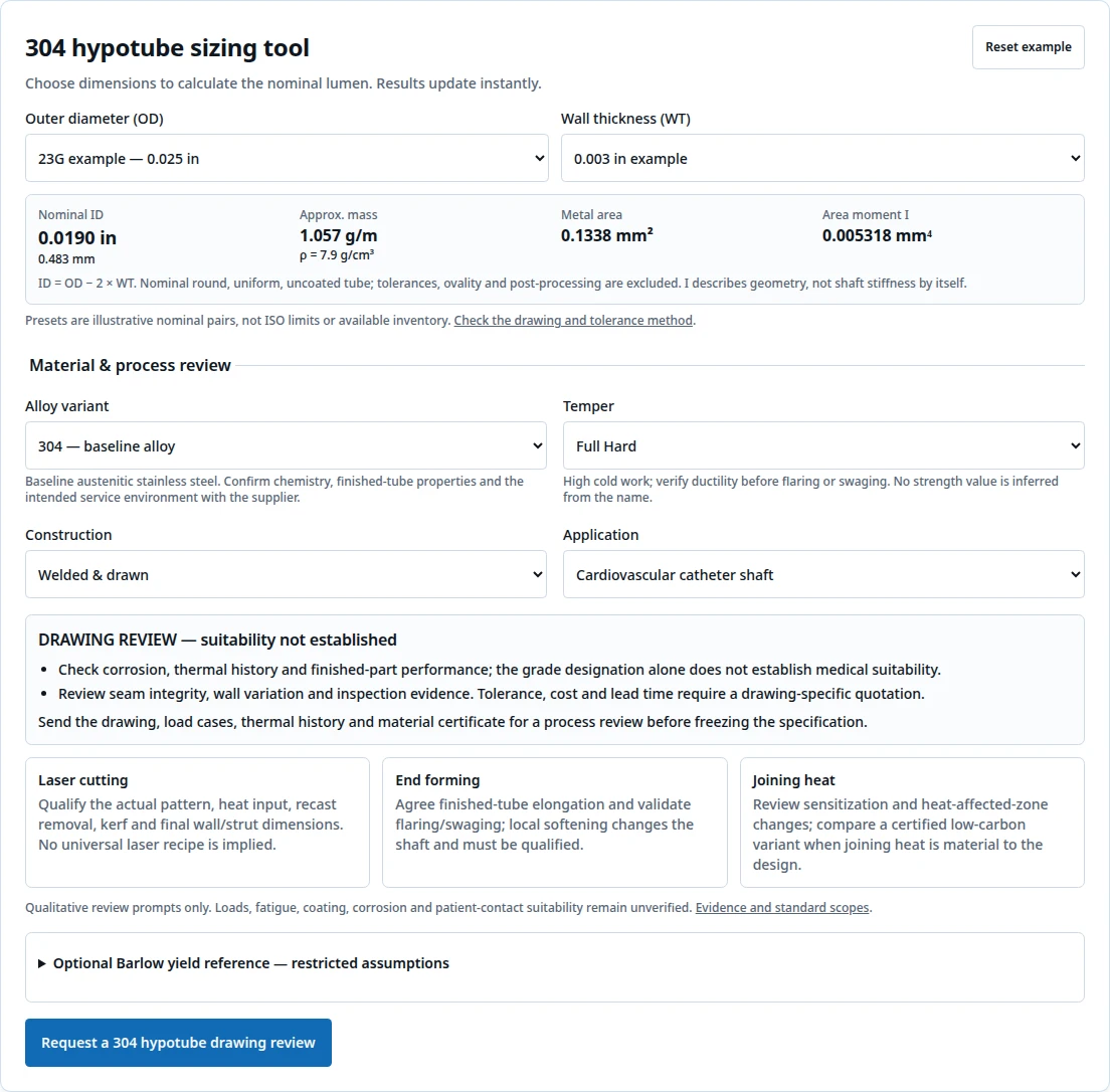
304 hypotube sizing tool
Choose dimensions to calculate the nominal lumen. Results update instantly.
Loading interactive controls. The example below remains readable.
ID = OD − 2 × WT. Nominal round, uniform, uncoated tube; tolerances, ovality and post-processing are excluded. I describes geometry, not shaft stiffness by itself.
Presets are illustrative nominal pairs, not ISO limits or available inventory. Check the drawing and tolerance method.
DRAWING REVIEW — suitability not established
- Check corrosion, thermal history and finished-part performance; the grade designation alone does not establish medical suitability.
- Review column loading, bending, joints and the complete catheter test plan.
- Review seam integrity, wall variation and inspection evidence. Tolerance, cost and lead time require a drawing-specific quotation.
Send the drawing, load cases, thermal history and material certificate for a process review before freezing the specification.
- Laser cutting
- Qualify the actual pattern, heat input, recast removal, kerf and final wall/strut dimensions. No universal laser recipe is implied.
- End forming
- Agree finished-tube elongation and validate flaring/swaging; local softening changes the shaft and must be qualified.
- Joining heat
- Review sensitization and heat-affected-zone changes; compare a certified low-carbon variant when joining heat is material to the design.
Qualitative review prompts only. Loads, fatigue, coating, corrosion and patient-contact suitability remain unverified. Evidence and standard scopes.
Optional Barlow yield reference — restricted assumptions
Most presets are outside this tool’s thin-wall policy; only the 19G 0.002 in wall preset meets WT/OD ≤ 0.05. Other presets still provide nominal geometry. Changing alloy, temper or construction clears yield input because the certificate context has changed.
P = 2 × yield × WT / OD. For an intact round tube under static internal pressure only. This page uses WT / OD ≤ 0.05 as a conservative screening policy. The result is neither allowable working pressure nor a burst rating; it has no safety factor, tolerances, joint or fatigue allowance.
Reference withheld: Confirm an intact, uncut round tube. Slotted, laser-cut and assembled shafts need another analysis.
1. Four decisions before drawing release
Decision summary: conclusion, evidence and next stepScroll horizontally on small screens; keyboard users can focus the table and use arrow keys.
| Decision | Evidence / limitation | Action |
|---|---|---|
| Size with OD and wall, not gauge alone | Nominal ID = OD − 2 × WT; neither ovality nor tolerance is included. | Specify final lumen and tolerance stack. |
| Separate alloy, carbon and melt requirements | Atlas 304/304L and Fort Wayne 304V datasheets describe different attributes and product forms. | Request chemistry and melt traceability. |
| Treat temper as a processing choice | Supplier-specific cold-work data do not establish universal tube properties. | Agree finished-tube tensile and elongation tests. |
| Match standards to the actual component | ISO 9626 excludes flexible tubing; ISO 10555-1 concerns the complete intravascular catheter. | Document applicable scopes and the device test plan. |
Evidence: Atlas alloy background, Fort Wayne 304V data, ISO 9626 scope and ISO 10555-1 scope. Process actions in this guide are review recommendations, not validated manufacturing instructions.
2. 304, 304L and 304V: separate the requirements
304 is a baseline austenitic alloy. 304L addresses low carbon; 304V addresses remelting. A supplier may offer combined low-carbon/remelt requirements, but the abbreviation alone is insufficient to specify them. Compare the actual heat certificate and product specification.
Alloy comparison — supplier examples, not universal tube limitsScroll horizontally on small screens; keyboard users can focus the table and use arrow keys.
| Variant | Published example | Unknown until agreed | Source |
|---|---|---|---|
| 304 / S30400 | Atlas bar: carbon ≤0.08 mass % | Finished-tube strength, melt route, surface and service performance | Atlas 304–304L, bar datasheet |
| 304L / S30403 | Atlas bar: carbon ≤0.03 mass % | Joint performance and corrosion after actual heat cycles | Atlas 304–304L, bar datasheet |
| 304V / S30400 | Fort Wayne: vacuum remelt, carbon ≤0.08 mass % | Tube cleanliness acceptance, fatigue and low-carbon requirement | Fort Wayne 304V, wire material data |
These are limited examples from Atlas (April 2006) and Fort Wayne Metals (undated). Do not transfer bar/wire acceptance limits to a tube purchase order without agreement. No universal inclusion severity or fatigue improvement is established by these sources.
3. Temper changes yield resistance; geometry still matters
Cold work can increase yield and tensile strength while reducing forming ductility. The relationship is product and process dependent. Elastic bending resistance depends on E × I: a harder temper does not by itself establish a higher elastic modulus or a more flexible shaft.
Temper review — qualitative guidance, no default strength constantsScroll horizontally on small screens; keyboard users can focus the table and use arrow keys.
| Condition | Review priority | Release evidence |
|---|---|---|
| Annealed | Forming sequence, permanent set and column loads | Finished-tube mechanical data and final shape tests |
| 1/4 Hard / 1/2 Hard | Balance forming with required load resistance | Agreed numerical yield, UTS and elongation criteria |
| Full Hard / Extra Full Hard | Ductility at flares, swages and welded zones | Sample trials, local heat effects and assembly tests |
Fort Wayne’s wire data illustrate a product-specific cold-work trend and explicitly qualify the results by test method and diameter. They are not finished-hypotube allowables.
4. Welded & drawn versus seamless
Construction decision — compare actual supplier evidenceScroll horizontally on small screens; keyboard users can focus the table and use arrow keys.
| Route | What to inspect | Commercial tradeoff |
|---|---|---|
| Welded & drawn | Seam condition, wall map, surface defects and agreed integrity tests | Drawing route, tooling and inspection affect cost; obtain a quote. |
| Seamless | Wall eccentricity, surface defects and agreed integrity tests | Availability and drawing schedule affect lead time; obtain a quote. |
Neither route guarantees a wall tolerance, concentricity percentage or pressure ratio. Request measured sample data against the same drawing. ASTM A632 covers both routes within its scope, but its title does not qualify every miniature tube or cold-worked condition.
5. Qualify the laser-cut geometry, not a generic recipe
Cutting a continuous tube into struts changes its load path. The sizing tool calculates the uncut cross-section only. Do not use its area moment or Barlow reference to rate a slotted shaft.
Laser process trial checklist — targets must come from the drawingScroll horizontally on small screens; keyboard users can focus the table and use arrow keys.
| Variable | Evidence to collect | Risk if omitted |
|---|---|---|
| Pattern, pitch and minimum strut | Final geometry measured after finishing | Local weak sections and lumen distortion |
| Pulse regime, heat input and assist gas | Actual trial record and defect inspection | Recast, oxidation and local property changes |
| Cleaning / electropolishing sequence | Material-removal allowance, edges and residue checks | Thin struts or retained contamination |
| Representative load history | Bending, torsion, axial and pressure tests as applicable | Nominal tube data mistaken for part performance |
Engineering review checklist. No verified universal kerf, heat-affected-zone size, gas pressure or cycle-time advantage is available for your drawing.
6. Forming and joints: test the completed assembly
High cold work can limit flaring ductility. Compare the actual flare ratio, wall, tooling and thermal sequence on samples. Local annealing, a softer zone or another hub design may be worth evaluating; none is a guaranteed correction.
Joining can change strength and corrosion response. Establish joint retention, leakage and relevant load acceptance criteria for the device. A weld strength from another tube size or joint cannot be carried into the design.
Background: Atlas alloy/forming guidance. Device scope: ISO 10555-1:2023. This page does not reproduce acceptance tables from the licensed standard or claim a joint margin.
7. Surface treatment and coatings need their own acceptance plan
Specify the surface condition at delivery and after cutting, joining and cleaning. Agree which surfaces can be measured, the roughness method, acceptable residues, edge condition and material-removal allowance. Coating thickness changes the fit and can change the effective lumen.
ASTM B912-26 is a reference for electropolishing/passivation. It does not supply a guaranteed fatigue gain or a final roughness for every hypotube. Use the controlled process specification rather than copying a generic acid recipe.
8. Nominal gauge examples and the tolerance stack
The calculator’s gauge labels identify illustrative nominal pairs. They are neither an ISO dimensional table nor a supplier stock list. Gauge alone does not fix the ID. Confirm dimensions and the measurement method on the controlled drawing.
Illustrative gauge / wall presets — inches with computed millimetre conversionScroll horizontally on small screens; keyboard users can focus the table and use arrow keys.
| Example | OD in (mm) | Wall in (mm) | Nominal ID in (mm) |
|---|---|---|---|
| 14G-RW | 0.0830 (2.1082) | 0.0090 (0.2286) | 0.0650 (1.6510) |
| 14G-TW | 0.0830 (2.1082) | 0.0060 (0.1524) | 0.0710 (1.8034) |
| 17G-RW | 0.0580 (1.4732) | 0.0060 (0.1524) | 0.0460 (1.1684) |
| 17G-TW | 0.0580 (1.4732) | 0.0040 (0.1016) | 0.0500 (1.2700) |
| 19G-RW | 0.0420 (1.0668) | 0.0050 (0.1270) | 0.0320 (0.8128) |
| 19G-TW | 0.0420 (1.0668) | 0.0030 (0.0762) | 0.0360 (0.9144) |
| 19G-XTW | 0.0420 (1.0668) | 0.0020 (0.0508) | 0.0380 (0.9652) |
| 21G-RW | 0.0320 (0.8128) | 0.0050 (0.1270) | 0.0220 (0.5588) |
| 21G-TW | 0.0320 (0.8128) | 0.0030 (0.0762) | 0.0260 (0.6604) |
| 23G-RW | 0.0250 (0.6350) | 0.0040 (0.1016) | 0.0170 (0.4318) |
| 23G-TW | 0.0250 (0.6350) | 0.0030 (0.0762) | 0.0190 (0.4826) |
| 23G-UTW | 0.0250 (0.6350) | 0.0020 (0.0508) | 0.0210 (0.5334) |
| 25G-RW | 0.0200 (0.5080) | 0.0035 (0.0889) | 0.0130 (0.3302) |
| 25G-TW | 0.0200 (0.5080) | 0.0025 (0.0635) | 0.0150 (0.3810) |
| 27G-RW | 0.0160 (0.4064) | 0.0030 (0.0762) | 0.0100 (0.2540) |
| 27G-TW | 0.0160 (0.4064) | 0.0020 (0.0508) | 0.0120 (0.3048) |
| 30G-RW | 0.0120 (0.3048) | 0.0025 (0.0635) | 0.0070 (0.1778) |
| 30G-TW | 0.0120 (0.3048) | 0.0015 (0.0381) | 0.0090 (0.2286) |
| 32G-TW | 0.0090 (0.2286) | 0.0015 (0.0381) | 0.0060 (0.1524) |
For a uniform round tube, a conservative dimensional stack is ID minimum = OD minimum − 2 × wall maximum. Add any internal coating or liner allowance and check actual ovality, eccentricity and measurement capability separately. A cross-section ID does not guarantee full-length pin-gauge passage; agree pin length and straightness checks. Negative or zero calculated clearance means the proposed stack cannot establish a usable lumen.
ISO 9626 provides rigid-needle dimensional context; it does not make these illustrative presets certified dimensions.
9. Alternatives and risks that affect procurement
Risk and alternative matrix — drawing-review recommendationsScroll horizontally on small screens; keyboard users can focus the table and use arrow keys.
| Risk / mismatch | Review or alternative | Evidence before release |
|---|---|---|
| Chloride exposure or crevices | Compare a corrosion-focused alternative such as 316L and the final surface process | Relevant environment / crevice testing; no grade-only guarantee |
| Large repeated bends | Compare cut patterns, another architecture or a suitable superelastic alloy | Finished-part fatigue and deformation tests |
| High cold work plus deep flare | Compare softer forming zone or alternative hub attachment | Forming trial and completed joint tests |
| Unnecessary melt / tolerance requirements | Tie every premium requirement to a documented failure mode | Separate sample, tooling, inspection and production quotations |
| Use of nominal data as a rating | Obtain minimum wall, maximum OD and a validated analysis/test method | Approved device-specific verification plan |
Atlas lists 316 as a possible corrosion-focused comparison. Other entries are design-review options; cost, fatigue and recovery performance are unknown until qualified. Public evidence here does not support universal cost premiums or a fatigue ranking.
10. Source register and scope boundaries
Public source pages checked on . The source register distinguishes background data from component and device scopes. Licensed clause-level acceptance criteria must be checked in the controlled standard and applicable market requirements.
- Atlas Steels: 304–304L bar datasheet (April 2006)
Background on alloy identity, low carbon, forming and chloride limitations. Bar data are not finished-hypotube acceptance values.
- Fort Wayne Metals: 304V material data (undated)
Supplier-specific VAR chemistry and typical wire properties. Its carbon maximum is 0.08%; 304V is not automatically low carbon. Wire results do not qualify a laser-cut tube.
- ASTM A632-19(2025): small-diameter tubing
General-service, heat-treated tubing. Public scope gives OD 0.050 to below 0.500 in and wall 0.005 to below 0.065 in; the default 23G example is outside those dimensional bounds.
- ISO 9626:2016: rigid needle tubing
Rigid stainless needle tubing requirements. Flexible tubing is outside scope; its dimensional guidance may still inform an agreed drawing. A revision is under development.
- ISO 10555-1:2023: intravascular catheters
General requirements for sterile single-use intravascular catheters, not a raw-tube material approval. Accessories have a different scope.
- ISO 10993-1:2025: biological safety evaluation
Biological evaluation within risk management. The finished device, processing and exposure must be considered; a grade label is insufficient.
- ASTM B912-26: electropolishing / passivation
Process specification reference. It does not establish a universal final roughness, material-removal allowance or fatigue improvement.
- Swagelok: Tubing Data, MS-01-107
Industrial reference showing pressure calculations based on maximum OD, minimum wall and method-specific assumptions. Its pressure tables are not medical-device ratings.
Many microtube presets fall outside A632 dimensional scope. For example, a 23G tube with 0.025 in OD and 0.003 in wall is below the public A632 minimum dimensions. If an order references selected A632 provisions by agreement, identify the departures explicitly. Do not call the entire tube conforming solely because the alloy is listed.
ISO 10993-1:2025 concerns biological safety evaluation within risk management. Raw-alloy chemistry, passivation or a material certificate does not establish finished-device biological safety.
11. Worked examples — hypothetical, not customer or clinical results
23G nominal lumen
Assume OD 0.025 in and wall 0.003 in. ID = 0.025 − 2 × 0.003 = 0.019 in = 0.4826 mm. Use this as a nominal fit starting point; apply the drawing tolerance stack next. The optional pressure reference is withheld because WT/OD = 0.12 exceeds this page’s screen.
Thin flexible shaft
Assume 27G example OD 0.016 in and wall 0.002 in: ID = 0.012 in (0.3048 mm). Select flexible shaft and annealed condition: both fatigue-evidence and load/permanent-set cautions remain visible. Changing to VAR does not certify either risk away.
Dimensional stack
Assume OD 0.025 ±0.0003 in and wall 0.003 ±0.0002 in. Uniform-round ID minimum = 0.0247 − 2 × 0.0032 = 0.0183 in (0.46482 mm). These invented drawing tolerances illustrate the arithmetic, not supplier capability. Add ovality, coating and clearance allowances separately.
Optional pressure arithmetic
Assume an intact tube, OD 0.100 in, wall 0.004 in and a hypothetical user-supplied yield of 500 MPa. WT/OD = 0.04; 2 × 500 × 0.004 / 0.100 = 40 MPa = 400 bar (about 5802 psi). This theoretical yield reference has no safety factor or assembly allowance and is not a working-pressure recommendation.
12. Drawing review and RFQ checklist
Minimum review package — acceptance values come from your controlled drawingScroll horizontally on small screens; keyboard users can focus the table and use arrow keys.
| Supply item | What to make explicit | Supplier response needed |
|---|---|---|
| Material and traceability | Alloy, carbon requirement, melt route and heat identity | Certificate, product specification and deviations |
| Dimensions | OD, ID or wall, tolerances, length, straightness and ovality | Measurement capability and final inspection method |
| Mechanical condition | Numerical yield / UTS / elongation criteria and test method | Finished-tube results; not strip or wire substitutes |
| Process history | Cut pattern, joining, local heat treatment and finishing sequence | Trial plan and change-control boundaries |
| Surface and packaging | Roughness method, edges, cleanliness, coating and protection | Final-state inspection and packaging proposal |
| Quantity and release plan | Prototype and production quantities, sampling, applicable standards | Separate tooling, samples, inspection, minimum order, protective packaging, lead time and exceptions |
When drawings are incomplete, the minimum alternative is to send an OD/wall sketch, intended load cases and process sequence for clarification. Keep capability, quote and acceptance decisions separate until the missing inputs are resolved.
13. Calculation method, assumptions and unknowns
What each result means — and what it cannot establishScroll horizontally on small screens; keyboard users can focus the table and use arrow keys.
| Output | Method / input | Limit |
|---|---|---|
| Nominal ID | OD − 2 × WT; inch × 25.4 = mm | Uniform round cross-section; no tolerances or coatings |
| Metal area A | π × WT × (OD − WT), using mm | Uncut tube only; excludes slots |
| Approximate linear mass | A × 7.9 g/m, using A in mm² | Rounded reference density 7.9 g/cm³ from Atlas background data; not lot-specific |
| Geometric moment I | π/64 × (OD⁴ − ID⁴), using mm | Not E × I, buckling load or fatigue life |
| Optional yield-pressure reference | P = 2 × user yield × WT / OD; 1 MPa ≈145.038 psi =10 bar | Intact tube, WT/OD ≤0.05 tool policy; no working or burst rating |
| Process prompts | Qualitative material / temper / application rules | No certification, validated failure threshold or prediction |
The pressure screen is a conservative page policy, not a pass/fail criterion from ASTM or ISO. If yield data are unavailable, leave the optional input blank and request a certificate. For a thick-wall, slotted or assembled component, use an appropriate engineering analysis and representative tests.
Pressure design needs a defined allowable stress, dimensional extremes, weld/joint treatment, environment and appropriate margins. Swagelok’s industrial tubing reference illustrates why nominal dimensions alone are insufficient; its tables are not transferred into this tool.
Unknowns retained explicitly: actual material properties, fatigue life, final surface condition, clinical performance, supplier tolerances, cost and lead time. No measured outcomes are implied by the worked examples or schematics.
14. Sizing, material, process and procurement FAQs
Sizing
What does 304 hypotube mean?
A small metal tube specified with 304 stainless chemistry. The designation does not define gauge, wall, temper, construction, surface condition or medical-device suitability.
Does 23G fix the lumen diameter?
No. The calculator uses an illustrative 0.025 in OD. Nominal ID depends on wall: 0.003 in wall gives 0.019 in ID. Agree the actual OD, wall and acceptance limits on the drawing.
Can I enter metric dimensions?
The inputs are in inches. Divide millimetres by 25.4 before entering; calculated ID is displayed in both units. Avoid mixing units in an RFQ.
What happens with empty or impossible dimensions?
The tool withholds geometry and process results, identifies the invalid field or wall/OD conflict, and offers a reset example. Wall must be positive and less than OD/2.
Material
When should I compare 304L with 304?
Compare a certified low-carbon grade when joining heat and sensitization matter. Then qualify the actual heat cycle, joint and corrosion performance; low carbon is not a universal process guarantee.
Is 304V the same as low-carbon 304L?
No. V identifies a vacuum-remelted variant. Supplier chemistry still governs; Fort Wayne Metals lists a 0.08% carbon maximum for its 304V. Specify low carbon separately when required.
Does VAR guarantee a longer fatigue life?
No. It can improve melt homogeneity and reduce inclusions, but the finished cut geometry, surface defects, loads and environment determine the part evidence needed. This page provides no tube fatigue-life prediction.
Does Full Hard mean a fixed yield strength?
No. Obtain numerical finished-tube yield, tensile and elongation requirements with test method and gauge length. This tool does not assign a strength value from a temper name.
Process
Can Full Hard tubing be flared?
High cold work can reduce forming ductility. Trial the actual geometry and tooling; compare a local forming zone, a softer condition or another hub design, then verify the completed assembly.
Is seamless always more pressure resistant?
No universal ranking is established here. Compare actual wall variation, defects, process history, inspection and pressure tests. No seamless multiplier or welded-tube derating is inferred by this calculator.
Can I copy a laser setting from this guide?
The guide supplies a trial checklist rather than a recipe. Qualify kerf, recast, thermal effects and final dimensions on the actual alloy, tube and cut pattern.
Does electropolishing restore a known fatigue limit?
No universal restoration value is established. Measure material removal and edge condition, confirm minimum strut/wall, and test fatigue under representative conditions if required.
Evidence
Why is the pressure reference sometimes withheld?
It needs valid dimensions, a user-supplied finished-tube yield value, an intact round tube and WT/OD at or below this page’s 0.05 screen. Thick-wall or cut shafts require a different analysis. Even a displayed reference is not allowable pressure.
Does ISO 9626 cover a flexible slotted shaft?
Its public scope excludes flexible stainless tubing. Dimensional guidance may be useful by agreement, but it cannot be presented as flexible-shaft qualification.
Is a material certificate enough for patient contact?
No. Biological evaluation considers the device, manufacturing residues, coatings and intended exposure within a risk-management process. A certificate supports traceability, not device approval.
Procurement
What should I send for a useful quotation?
Send the controlled drawing, dimensions and tolerances, material and melt requirements, finished-tube properties, process sequence, inspection plan, quantities and intended use. Ask suppliers to identify deviations, tooling, sample costs and lead time.
Turn the nominal size into a reviewable specification
Send your drawing, material certificate if available, quantities and intended process sequence. Identify the dimensions and evidence still needing confirmation.
Submit a 304 hypotube drawing