
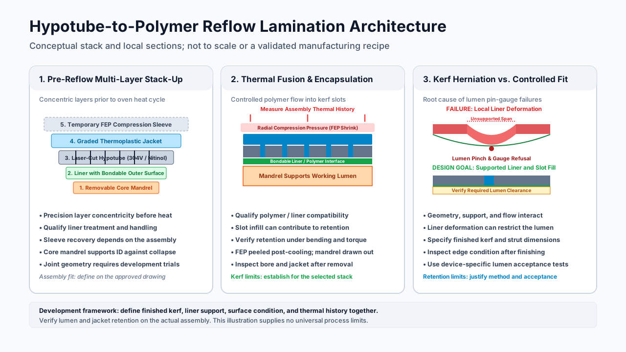
Hypotube-to-Polymer Reflow Lamination: Preventing Kerf Herniation, Jacket Delamination, and Lumen Collapse in Catheter Manufacturing
Hypotube-to-polymer reflow lamination: compare jacket materials, diagnose shaft defects, and prepare drawing-based RFQs. Request a catheter shaft DFM review.
Hypotube-to-polymer reflow lamination uses heat and external compression to consolidate a thermoplastic jacket around a laser-cut metallic catheter shaft. A supported inner liner preserves the working lumen while polymer flows around the metal structure. The engineering challenge is to obtain useful retention without driving material into the lumen, damaging the liner, or creating a weak stiffness transition.
For catheter design engineers, manufacturing teams, and procurement specialists, three questions should drive the specification: What geometry must remain open after reflow? What retains the jacket during bending and withdrawal? What evidence will demonstrate that the selected metal, polymer, and tooling work together? Narrower slots, a hotter oven, or a harder jacket alone cannot answer all three.
The primary failure mechanisms during thermal reflow are:
- Kerf herniation (squeeze-through): Polymer flow through laser slots deforms an inadequately supported liner, creating local lumen restrictions.
- Interfacial delamination: Inadequate retention, contamination, or an unsuitable interface allows the jacket to peel or move relative to the metal.
- Mandrel sticking and lumen ovality: Tooling fit, release condition, and thermal contraction can cause extraction damage or a distorted bore.
- Durometer transition kinking: A poorly consolidated jacket junction or abrupt combined metal/polymer stiffness change creates a local weak point.
Scope and evidence — Published and reviewed November 9, 2026: This guide is a DFM and purchasing framework for global OEM and CDMO teams considering lined, thermoplastic-jacketed laser-cut shafts. The diagnostic tables and drawing checklist are engineering planning recommendations, not results from a validated production lot. No universal kerf limit, reflow recipe, scrap-rate improvement, or clinical suitability is claimed. Apply device-specific risk assessment, controlled material documentation, and process validation; market-specific regulatory requirements remain the device manufacturer's responsibility.
Review our laser-cut hypotube manufacturing overview, balloon catheter shaft applications, and neurovascular catheter components. For a component DFM review, send the drawing, liner/jacket details, and lumen requirements to our engineering team.
1. The Multi-Layer Catheter Stack-Up: Mechanics of Thermal Fusion
A lined catheter shaft can be understood from the center outward. The following stack is illustrative; other constructions may use braid, coil reinforcement, different liners, or a different processing sleeve.
Center: removable core mandrel
    -> Inner lubricious liner, with a bondable outer surface where needed
    -> Laser-cut stainless steel or Nitinol hypotube
    -> Optional compatible tie layer or surface treatment
    -> Thermoplastic jacket, potentially with multiple hardness zones
    -> Temporary heat-shrink compression sleeve, removed after processing
Illustrative product image; not a cross-section, inspection record, or customer lot release result.
The Five Concentric Elements
- Core mandrel: A solid coated mandrel or a removable wire supports the bore. Its diameter, straightness, coating condition, thermal behavior, and extraction method all affect the finished lumen. Select the tooling together with the liner rather than assuming the nominal mandrel diameter equals the final catheter ID.
- Inner lubricious liner: PTFE is one option; other designs use polyimide or alternative liner materials. Untreated PTFE is difficult to bond. Where the construction requires bonding to PTFE, specify a supplier-qualified outer surface treatment or bondable layer while preserving the intended lumen surface. Track treatment date, storage, and handling restrictions.
- Laser-cut metallic hypotube: Stainless steel or Nitinol provides structural support. Slot width, cut pitch, remaining strut dimensions, and edge condition affect bending and polymer retention. The relevant dimensions are those after finishing, because deburring or electropolishing can alter both slots and struts.
- Outer thermoplastic jacket: Polyether block amide (PEBA, including Pebax-branded grades), nylon, and thermoplastic polyurethane are candidate families. Resin grade, extrusion dimensions, additives, moisture condition, and processing history matter alongside nominal hardness. Hardness alone does not establish melt behavior or adhesion.
- Temporary compression sleeve: FEP heat-shrink tubing is a processing option. Its recovery behavior must overlap the chosen jacket's processing window without damaging the liner. Recovery ratio is a dimensional descriptor, not a direct measurement of pressure on the assembly. Removal must avoid scoring the jacket or leaving sleeve fragments.
2. Reflow Architecture: Multi-Layer Assembly & Defect Prevention
The schematic illustrates the stack, polymer flow into slots during consolidation, and the difference between a supported and a locally restricted lumen. It is a conceptual diagram, not a scale drawing or evidence of a qualified process window. An optional tie layer is not depicted separately.
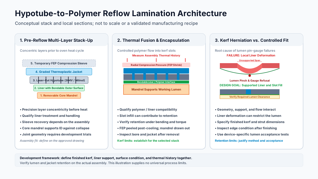
Figure 1: Illustrated layer stack and local sectional details. Dimensions, temperatures, and acceptance limits must come from the approved device drawing and process study.
A useful development record separates three observations: the metal geometry before assembly, the thermal history experienced by the assembled shaft, and the lumen/jacket condition after cooling and mandrel extraction. Without this separation, a damaged liner can be mistaken for excessive polymer flow, and an extraction defect can be mistaken for an oven defect.
3. The Four Primary Reflow Failure Modes: Physics, Root Causes, and Mitigation
Defect 1: Kerf Herniation (Polymer Squeeze-Through into the Lumen)
Molten jacket resin can enter laser slots as the sleeve recovers. Filling a slot may contribute to retention, but inward liner displacement is undesirable when it reduces the required lumen clearance. Wider unsupported spans, a damaged liner, unsuitable tooling clearance, and excessive local flow are competing explanations; none can be diagnosed from slot width alone.
Measure the narrowest usable lumen after extraction and correlate restrictions with the cut pattern. Section representative straight regions and transitions, using micro-CT where its resolution and material contrast are adequate. A passage gauge checks clearance along the path it traverses, but does not quantify wall thickness or identify every liner defect.
Compare controlled trials of finished kerf geometry, liner/mandrel fit, and thermal exposure. Do not adopt a universal micrometer cutoff or reduce temperature by a fixed amount without checking consolidation and jacket retention. A change that opens the lumen but leaves unbonded interfaces has only moved the defect.
Defect 2: Interfacial Delamination & Peel Failure (Metal-to-Polymer Separation)
A smooth metal surface does not by itself establish a durable polymer bond. Retention can involve mechanical encapsulation, compatible tie layers, and qualified surface treatments. Residual drawing oil, loose particulate, moisture, and handling contamination can interfere with that interface.
Inspect the failure surface before changing the recipe. Clean separation from metal suggests a different investigation from cohesive tearing within the polymer or separation at the liner. Compare cleaning records, treatment age, material lots, and the location of the defect. Record whether damage appears immediately after reflow or only after bending, sterilization, or aging.
Plasma treatment, primers, and interlocking cut features are development options rather than interchangeable fixes. A primer introduces another material and process to qualify; a cut change also changes stiffness and fatigue behavior. Test the complete construction after the relevant conditioning rather than treating initial peel force as a complete durability assessment.
Defect 3: Mandrel Sticking, Lumen Ovality, and Elongation
High extraction force can arise from liner damage, polymer flash, an unsuitable release surface, or thermal contraction around the tooling. Pulling harder can stretch the shaft, change laser-cut pitch, or score the lumen. Record extraction force and compare shaft length and lumen condition before and after removal.
A draw-down wire mandrel may reduce diameter during controlled elongation, while a coated solid mandrel offers another approach. Neither provides guaranteed friction-free removal. Tooling selection depends on length, bore size, coating integrity, gripping method, and acceptable residual contamination. Define the removal sequence and allowable force during development, including how the shaft is supported.
Measure the bore rather than relying on outer diameter alone. An external laser micrometer can reveal OD changes but cannot establish the internal lumen profile through an opaque metal-reinforced shaft. Combine passage checks with suitable internal imaging or sectioning where lumen ovality is critical.
Defect 4: Durometer Step-Down Kinking and Trapped Air Voids
Adjacent jacket segments must consolidate without leaving an annular gap or excessive local thinning. Their junction also interacts with the termination of the metal cut pattern. Aligning a polymer junction with an abrupt metal stiffness change may concentrate bending in a short region.
Compare butt, scarf, or overlap joints using the actual extruded grades. Specify the geometry that survives dimensional and bend testing; no single scarf angle or overlap length is appropriate for every shaft. Evaluate air escape and heating direction against the actual assembly sequence. Moisture-related voids require a different corrective action from geometrically trapped air.
Use the resin or tubing supplier's drying and storage instructions. A generic bake temperature and duration can under-dry one grade or damage another. Record material exposure after drying and avoid interpreting a visually smooth jacket as proof that the internal junction is complete.
4. Polymer Selection & Reflow Processing Window Matrix
Use this selection matrix to request the information needed for trials. It deliberately avoids generic oven setpoints: the indicated heater temperature can differ from the temperature at the polymer/metal interface, especially when mandrel mass or line speed changes.
| Material or process element | Candidate role | Information to obtain | Main reflow concern | Decision before supplier approval |
|---|---|---|---|---|
| Higher-hardness PEBA jacket | Proximal shaft support | Exact grade, extrusion dimensions, thermal and rheological data | Consolidation without damaging adjacent softer sections | Confirm shaft stiffness and lumen clearance together |
| Intermediate-hardness PEBA jacket | Stiffness transition | Compatibility with adjoining grades and joint geometry | Incomplete fusion or a local stiffness step | Compare conditioned joints in the intended bend configuration |
| Lower-hardness PEBA jacket | Flexible distal section | Grade-specific flow, thickness, and handling requirements | Local thinning, flow through slots, or poor support | Verify retained wall and lumen after extraction |
| Polyamide jacket, such as PA12 | Candidate structural jacket | Moisture control, processing limits, and interface compatibility | Moisture voids and dimensional changes | Qualify drying, consolidation, and retention for that grade |
| Thermoplastic polyurethane jacket | Candidate compliant jacket | Polymer chemistry, thermal stability, and release behavior | Tack, degradation, or difficult tooling removal | Evaluate extraction and aged mechanical behavior |
| PTFE or alternative liner | Working lumen surface | Treatment, bondable outer layer, shelf life, and wall tolerance | Liner deformation, puncture, or interface separation | Confirm bore integrity after the complete process |
| FEP compression sleeve | Temporary processing aid | Expanded/recovered dimensions and supplier recovery profile | Uneven compression, incompatible thermal window, removal damage | Verify recovery on the actual stack and complete removal |
Engineering selection framework, not a manufacturer datasheet comparison. Obtain revision-controlled data for the exact grades and tubing lots before setting process limits. A listed material family is not a claim of biological suitability, sterilization compatibility, or approved use in a finished device.
5. Reflow Defect Root-Cause & Countermeasure Diagnostic Matrix
Treat these as hypotheses to investigate. Record the defect location, material lots, tooling ID, and process revision before making changes, so the corrective action can be linked to evidence.
| Defect | Observable symptom | Candidate causes | Discriminating check | Controlled next action |
|---|---|---|---|---|
| Kerf herniation | Local lumen restriction near slots | Unsupported liner, damaged liner, excessive flow | Correlate bore sections with finished kerf geometry | Compare geometry and support at recorded thermal conditions |
| Interfacial delamination | Jacket lifts, wrinkles, or slides | Contamination, poor retention, incompatible interface | Inspect failure surfaces before and after conditioning | Compare cleaning/treatment variants with retention tests |
| Lumen ovality | Bore clearance varies with orientation | Tooling fit, asymmetric stack, nonuniform heating | Use internal sections or qualified imaging; OD alone is insufficient | Control alignment and compare bore profiles |
| Mandrel sticking | High pull force or shaft elongation | Release damage, flash, contraction | Log extraction force, length change, and liner condition | Evaluate support, removal sequence, and tooling surface |
| Transition notch | Kink at jacket junction | Poor fusion or coincident stiffness steps | Inspect junction sections and conditioned bend response | Compare joint placement and geometry |
| Surface pits or voids | Blisters, bubbles, or pinholes | Moisture, contamination, trapped air | Compare drying records and void location | Apply grade-specific drying and evaluate air escape |
| Thermal degradation | Discoloration or loss of strength | Excessive exposure or incompatible materials | Correlate measured thermal history with mechanical results | Re-establish the thermal window and check consolidation |
Before ordering another sample iteration, request a drawing review with the defect location, finished kerf measurements, and planned acceptance tests. Identify which party owns reflow development and which supplies only the metal component.
6. Specifying Laser-Cut Hypotubes for Reflow: Drawing-Based RFQ Checklist
An RFQ should control the interface between the supplied hypotube and the downstream lamination operation. A quotation based only on OD, ID, and length leaves important assumptions unresolved. Use the following checklist as drawing-review prompts; numerical limits must be justified by the device design and trial results.
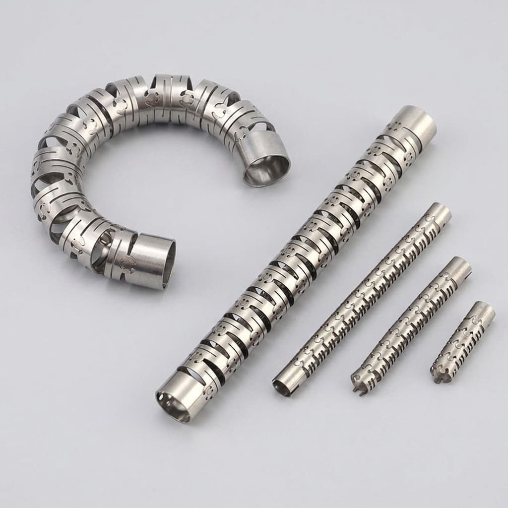
Illustrative product image; edge quality, cleanliness, and dimensions require separate inspection evidence.
Laser Kerf Width & Geometry
- State nominal slot width, tolerance, taper, pitch, and remaining strut dimensions after all finishing operations.
- Identify critical locations and the measurement method, including how narrow slots will be inspected.
- Request representative finished samples; assess laser technology through resulting edge quality and geometry rather than requiring one laser type for every design.
Edge Deburring & Radiusing
- Define allowable burrs, edge condition, and inspection magnification or resolution on both ID and OD.
- Specify any edge-radius requirement together with minimum remaining strut dimensions.
- Evaluate whether finished edges damage the actual liner or processing sleeve under assembly and reflow conditions.
Surface Cleanliness & Treatment
- Define cleaning, residue-control, handling, packaging, and traceability requirements appropriate to the assembly.
- Identify any passivation, primer, plasma, or tie-layer process and its responsible supplier.
- Require compatibility evidence for the chosen metal, including Nitinol-specific treatment where applicable; do not transfer stainless steel finishing requirements automatically.
Dimensional Concentricity & Straightness
- Include OD, ID, wall variation, ovality, and straightness limits with defined measurement conditions.
- State liner and mandrel tolerances so the assembly fit can be reviewed as a stack.
- Separate metal-component inspection from finished-catheter lumen acceptance; passing one does not establish the other.
Transition Zone Mapping & Change Control
- Map cut-pattern changes, metal termination, jacket grades, and polymer junction locations on a shared axial datum.
- Define prototype variants, quantity per variant, required reports, and agreed lead time.
- Require approval before changes to resin grade, cutting, finishing, cleaning, tooling, or subcontractors that could affect the interface.
For comparable quotations, state whether pricing includes metal only, finishing and inspection, or assembled reflow trials. Ask suppliers to separate setup, prototype variants, destructive inspection, and production documentation. An inexpensive tube quotation can omit the evidence needed to qualify the assembled shaft; the scope must be clear before comparing unit prices.
7. Mechanical Verification, Inspection, and Regulatory Testing
ISO 10555-1:2023 addresses general requirements for sterile, single-use intravascular catheters. Select applicable requirements using the controlled standard and the intended device. This guide does not reproduce its test conditions, diameter-dependent limits, or annex procedures. A component drawing and an acceptable cosmetic inspection cannot establish finished-device compliance.
A. Tensile and Joint Strength Testing
Define which shaft sections and transitions will be tested, how specimens are conditioned, how they are gripped, and what failure modes are acceptable. Derive loads and methods from applicable requirements and the device risk analysis. Record location and mode of failure as well as peak force; a strong jacket can conceal a weak junction elsewhere.
B. Interfacial Retention and Peel Resistance
The cited ASTM D3167-10(2017) record concerns floating roller peel resistance of adhesives. It is a historical edition, not a catheter-specific acceptance specification. Verify the applicable edition and specimen requirements before using it. A modified test on a narrow tubular jacket needs a documented fixture, specimen preparation, repeatability, and limitations; do not label an adapted method as unmodified ASTM compliance or assign a universal peel-force threshold.
C. Leakage, Pressure, and Lumen Integrity
Choose leakage and pressure tests appropriate to the intended use and labeling. A non-power-injectable catheter must not inherit a power-injection rating from its jacket material or a component burst result. Evaluate the assembled structure, transitions, and connectors under the selected conditions. A passage gauge addresses clearance, while leakage testing addresses a different failure mechanism; neither substitutes for the other.
D. Simulated Use, Fatigue, and Process Validation
Select bend geometry, cycle count, temperature, accessories, and conditioning to represent intended use and justified worst cases. Inspect for delamination, liner damage, particles, and permanent lumen restriction after testing. Include relevant sterilization and aging conditions in the verification plan rather than relying exclusively on newly made samples.
Use the manufacturer's quality system and the applicable ISO 13485:2016 framework to determine and document validation needs. Where subsequent inspection cannot fully verify process results, define the necessary validation, monitoring, and change control. This article does not claim that any supplier is certified or that a generic IQ/OQ/PQ checklist establishes device approval.
For development trials, preserve a repeatable evidence chain: drawing revision, material and surface-treatment lots, tooling ID, measured thermal history, extraction record, inspection images, and mechanical results. Predefine the sample plan and acceptance criteria. A successful prototype demonstrates feasibility under its tested conditions; it does not establish production capability across lots, operators, and equipment.
8. Sourcing & Supplier Selection: Evaluating Catheter Manufacturing Partners
Evaluate suppliers against the interface risks rather than broad capability claims:
- Finished cutting quality: Request representative microscopy and dimensional reports after secondary finishing. Laser type is relevant process information, but does not alone prove acceptable burrs, fatigue behavior, or compatibility with a thin liner.
- Finishing and subcontractor control: Ask who performs deburring, electropolishing, cleaning, and packaging. In-house processing and controlled subcontracting can both be viable; assess records, traceability, dimensional impact, and change notification.
- Handling and packaging: Agree on contamination controls and packaging that protect fragile cut sections. A cleanroom classification alone does not demonstrate residue limits or a clean finished component. Specify the evidence relevant to your receiving and assembly process.
- Development handoff: Agree on trial variants, quantities, inspection deliverables, and lead times in writing. A metal supplier's DFM review should not be assumed to include polymer selection, full reflow development, or finished-device validation.
Make the prototype purchase order reference the same drawing and acceptance plan as the quotation. Reserve a documented decision point before production release, especially if a geometry change resolves one defect while changing stiffness, retention, or fatigue elsewhere.
9. Frequently Asked Questions (FAQ)
What is the maximum acceptable laser kerf width to prevent polymer herniation?
There is no universal limit for all catheter constructions. Finished slot geometry, liner support, resin flow, sleeve recovery, and thermal exposure interact. Establish a permissible range through controlled trials, then verify lumen clearance and jacket retention together. A published micrometer value without a matching stack and method is not a release criterion.
Can you reflow polymer directly over a Nitinol hypotube without a tie layer?
Some designs can use mechanical encapsulation, but direct reflow does not establish adequate retention. Compare untreated and treated interfaces as appropriate, inspect failure surfaces, and test after relevant conditioning. A tie layer or primer introduces additional compatibility and biological-evaluation considerations; its use should follow evidence for the complete assembly.
Is silver-plated copper wire always better than a solid steel mandrel?
No. A draw-down wire can facilitate removal in a suitable process, while a coated solid mandrel may suit another bore, length, or handling method. Compare extraction force, dimensional stability, surface condition, and liner damage. Do not assume uniform diameter reduction or zero extraction risk from the wire material alone.
What is the purpose of treating the PTFE liner, and how does it affect shelf life?
Treatment can make the liner's outer surface more bondable while retaining the intended lumen surface. The appropriate treatment, storage conditions, and usable life depend on the supplied product. Request lot-specific treatment information and supplier storage instructions; there is no single shelf-life allowance for every etched liner.
How does electropolishing affect reflow lamination?
It can improve edge condition and reduce features that might damage a liner, but it also removes metal and can change kerf width or strut dimensions. Specify and inspect the finished geometry. Electropolishing alone does not prove cleanliness, adhesion, or a particular yield improvement.
What causes jacket blistering or trapped micro-bubbles after reflow?
Possible causes include absorbed moisture, contamination, and air trapped during consolidation. Compare material drying/exposure records and the location of voids before selecting a remedy. Follow grade-specific drying instructions and evaluate venting or heating sequence on the actual stack; a single universal bake cycle is not appropriate.
10. Engineering Next Steps
Treat the hypotube, liner, jacket, compression sleeve, and mandrel as one manufacturing system. Define the required lumen, retained jacket geometry, transition behavior, and inspection evidence before freezing a recipe. The useful outcome of a trial is a documented relationship between controlled inputs and acceptable results, with unresolved risks identified for the next development stage.
For a component sourcing discussion, review our laser-cut hypotube capabilities, balloon catheter applications, and neurovascular component applications. Then request a drawing-based DFM review with the drawing revision, metal specification, liner and jacket grades, target lumen, prototype quantity, and known defects. Ask which component tolerances are feasible and what sample evidence can be supplied; agree separately on any reflow trial or validation scope.
References & Authoritative Sources
The sources below define standards context. They do not substantiate a universal kerf threshold, material recipe, or production-yield claim. Public catalogue records do not replace controlled copies of the applicable standards.
- ISO 10555-1:2023 — General requirements for sterile, single-use intravascular catheters. Use to identify applicable finished-catheter requirements; the standard's scope does not turn this DFM guide into a compliance test procedure.
- ASTM D3167-10(2017) — Floating Roller Peel Resistance of Adhesives. Historical edition cited for method context. Confirm the appropriate edition and the suitability of the specimen geometry before designing a tubular-jacket retention test.
- ISO 13485:2016 — Medical device quality management systems. Quality-system context for manufacturing controls and validation planning; certification or conformity must be established separately for the relevant organization and scope.
Author

Categories
More Posts
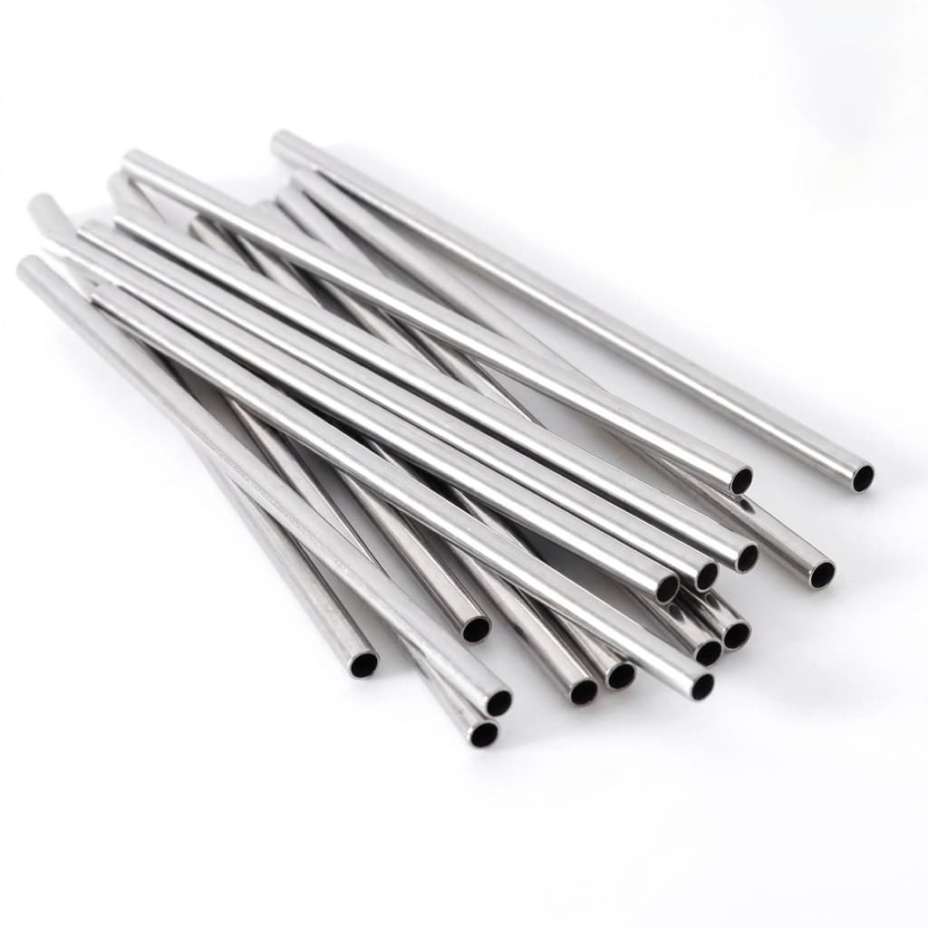
Electropolishing Medical Hypotubes: Why Burr-Free Surface Finishing Matters
Discover why electropolishing is a critical post-processing step for laser-cut medical tubing, detailing Ra surface roughness targets, fatigue resistance, and burr-free inspection standards.

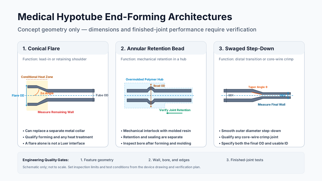
Medical Hypotube End-Forming: Flaring, Swaging, Bulging vs. Welded Hub Collars in Catheter Design and Sourcing
Compare medical hypotube end-forming, welded collars, and bonded hubs. Review forming risks, wall thinning and verification inputs; prepare a drawing-based RFQ.
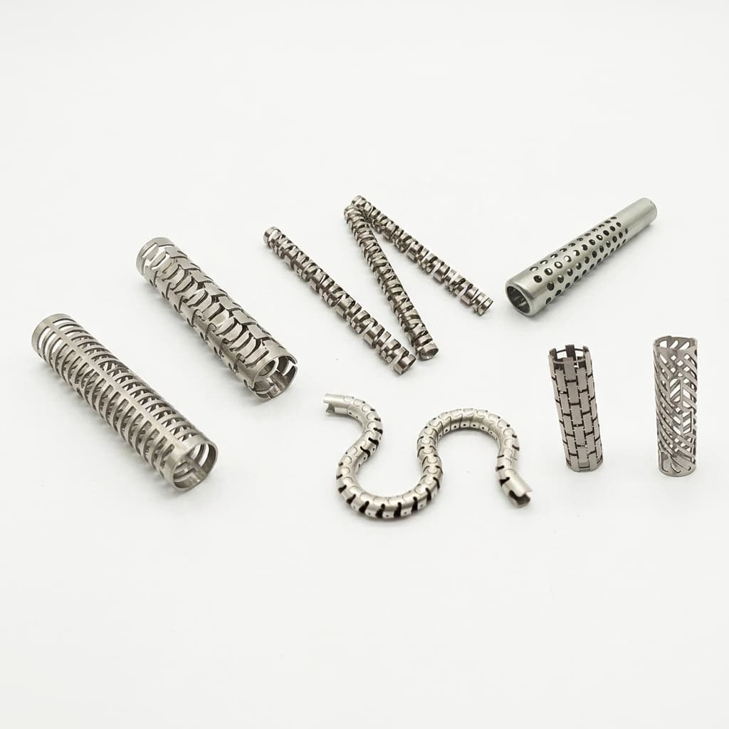
How to Specify Medical Hypotube Tolerances to Reduce Cost and Lead Times
Medical hypotube tolerances guide for RFQ teams: set OD, ID, wall, concentricity, straightness, and finish limits before you request a supplier DFM review.